SECTION 5 - REMOVAL - REFITTING OF THE MAIN ENGINE COMPONENTS
47
CURSOR SERIES
Print P4D32C006 E Base - 03/2015
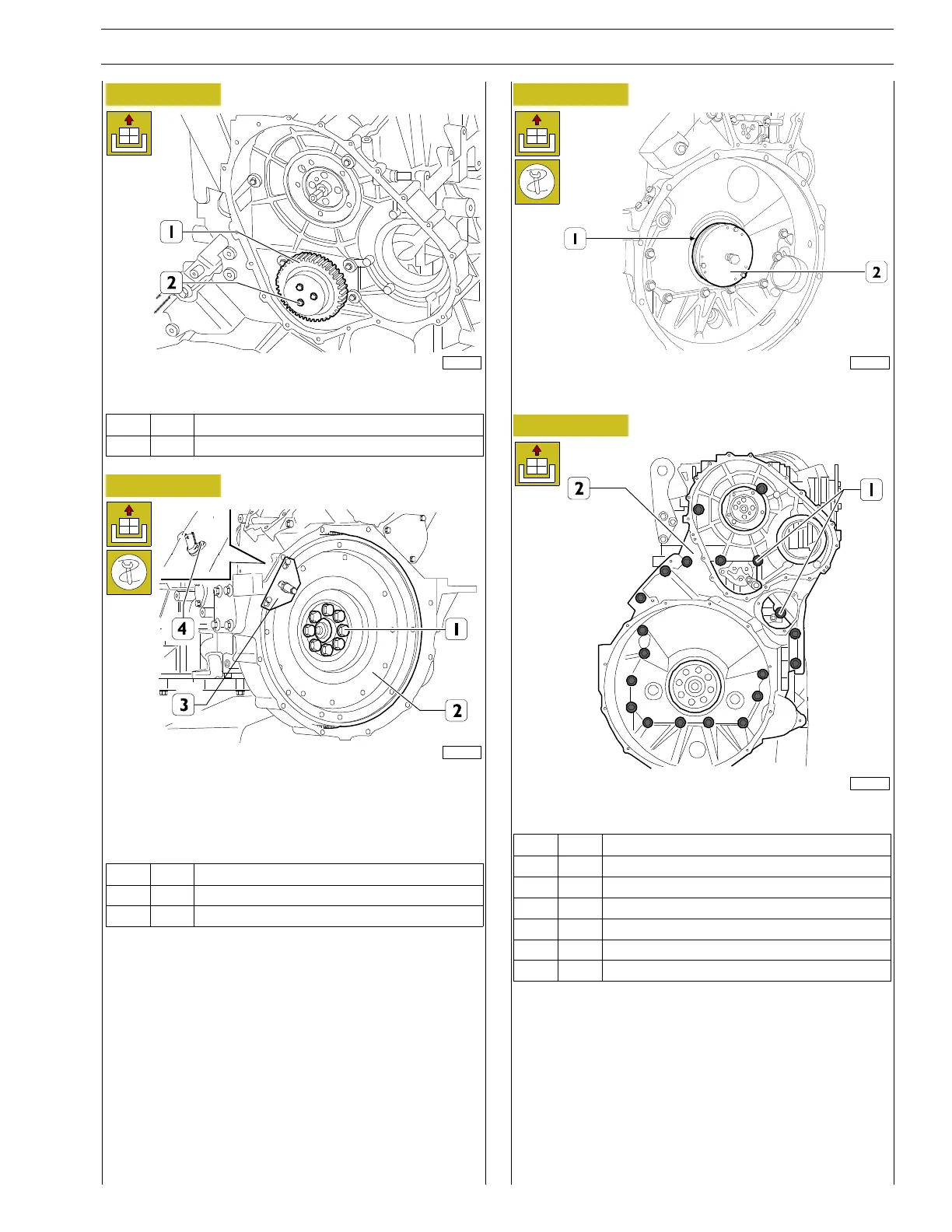
Figure 137
221107
Unscrew the screws (2) and remove the transmission gear (1).
Ref.
No. Description
(2) 3 Screws M12 X 1.75 X 110
Figure 138
225056
Unscrew the screw and remove the rpm sensor (4).
Using the tool 99360351 to lock the mounted engine flywheel
(3) unscrew the retaining screws (1); then remove the tool (3)
and remove the engine flywheel (2).
Ref.
No. Description
(1) 8 Screws M18 X 1.5 X 72
(4) 1 M6 x 12 screw
Figure 139
60500
Fit puller 99340053 (2) and take off the seal (1).
Figure 140
225018
Unscrew the screws (1) and remove the flywheel case (2).
Ref.
No. Description
(1) 10 Screws M12 X 1.75 X 100
(1) 4 Screws M12 X 1.75 X 40
(1) 1 Screws M12 X 1.75 X 120
(1) 2 Screws M12 X 1.75 X 193
(1) 2 Screws M12 X 1.75 X 70
(1) 2 Screws M10 X 1.5 X 30