SECTION 5 - REMOVAL - REFITTING OF THE MAIN ENGINE COMPONENTS
11
CURSOR SERIES
Print P4D32C006 E Base - 03/2015
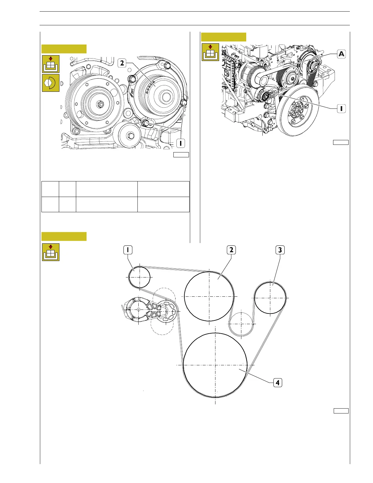
Refitting
Figure 22
224087
Fit the water pump (2) together with the new gasket and
tighten the screws (1) to the torque indicated in the table.
Ref.
No. Description
Tightening
torques
(1) 3
Screws M8 X 1.25 X
20
25 ± 2.5 Nm
Figure 23
225040
Using a 1/2 inch square wrench, operate on the belt tensioner
(1) and position the control belt of the crankshaft /
electromagnetic coupling / water pump / alternator (A)
pulley.
Refit the fan as described in the procedure ”FAN REMOVAL
- REFITTING”.
Refit the radiator assembly as described in the procedure
”RADIATOR ASSEMBLY REMOVAL - REFITTING”.
Refit the protection grilles as described in the procedure
”PROTECTION GRILL REMOVAL - REFITTING”.
Figure 24
150675
ASSEMBLY DIAGRAM OF THE PULLEY - WATER PUMP - ALTERNATOR DRIVE BELT
1. Alternator - 2. Electromagnetic coupling - 3. Water pump - 4. Crankshaft