SECTION 5 - REMOVAL - REFITTING OF THE MAIN ENGINE COMPONENTS
13
CURSOR SERIES
Print P4D32C006 E Base - 03/2015
Figure 29
225046
Fit the pulley electromagnetic coupling assembly (2) and
tighten the screws (1) to the torque indicated in the table.
Ref.
No. Description
Tightening
torques
(1) 5 Screws M12 X 1.75 100 ± 5 Nm
Figure 30
225040
Using a 1/2 inch square wrench, operate on the belt tensioner
(1) and position the control belt of the crankshaft /
electromagnetic coupling / water pump / alternator (A)
pulley.
Refit the fan as described in the procedure ”FAN REMOVAL
- REFITTING”.
Refit the radiator assembly as described in the procedure
”RADIATOR ASSEMBLY REMOVAL - REFITTING”.
Refit the protection grilles as described in the procedure
”PROTECTION GRILL REMOVAL - REFITTING”.
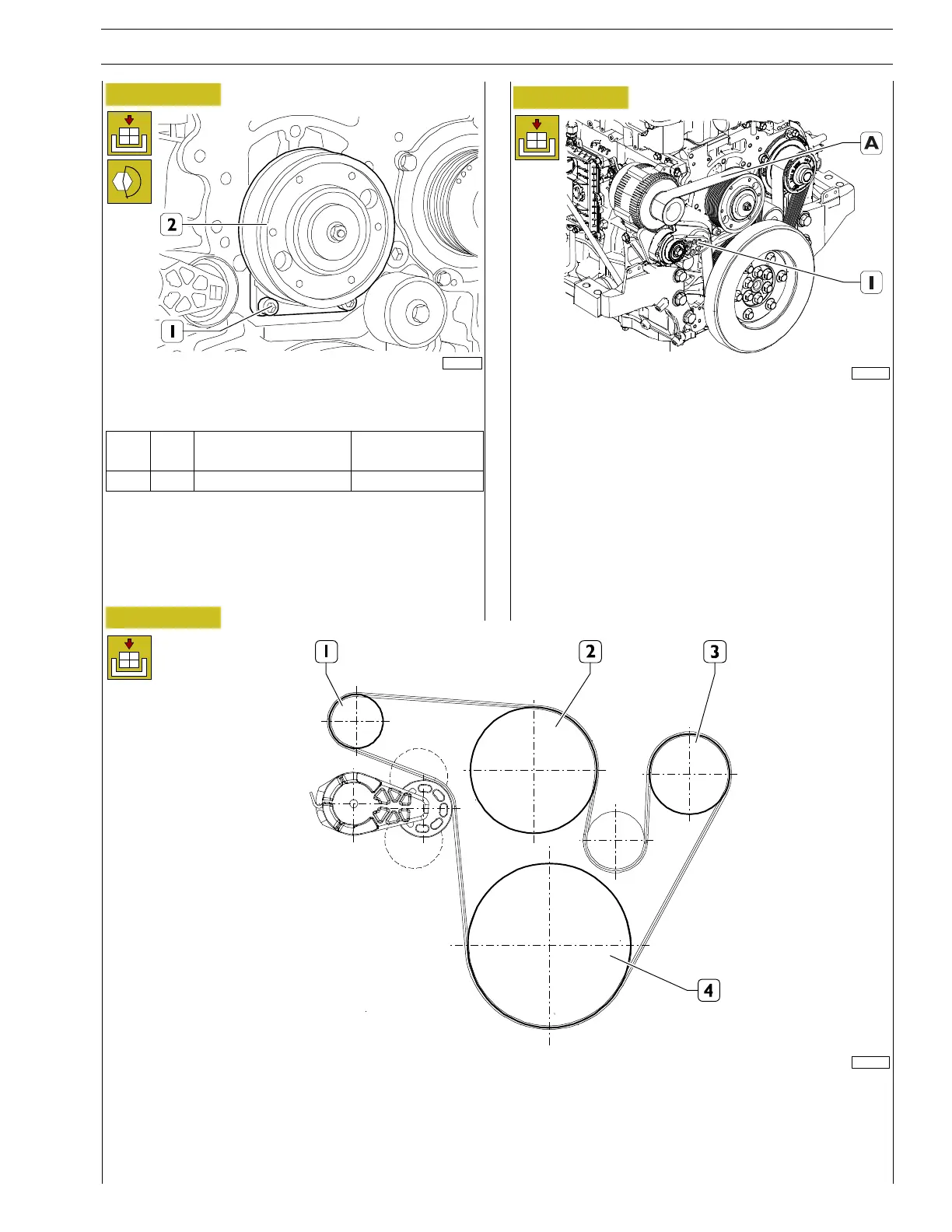
Figure 31
150675
ASSEMBLY DIAGRAM OF THE PULLEY - WATER PUMP - ALTERNATOR DRIVE BELT
1. Alternator - 2. Electromagnetic coupling - 3. Water pump - 4. Crankshaft