2/3
4. Troubleshooting
4302
4302
Diagnosis appendix: Diagnosis flowchart
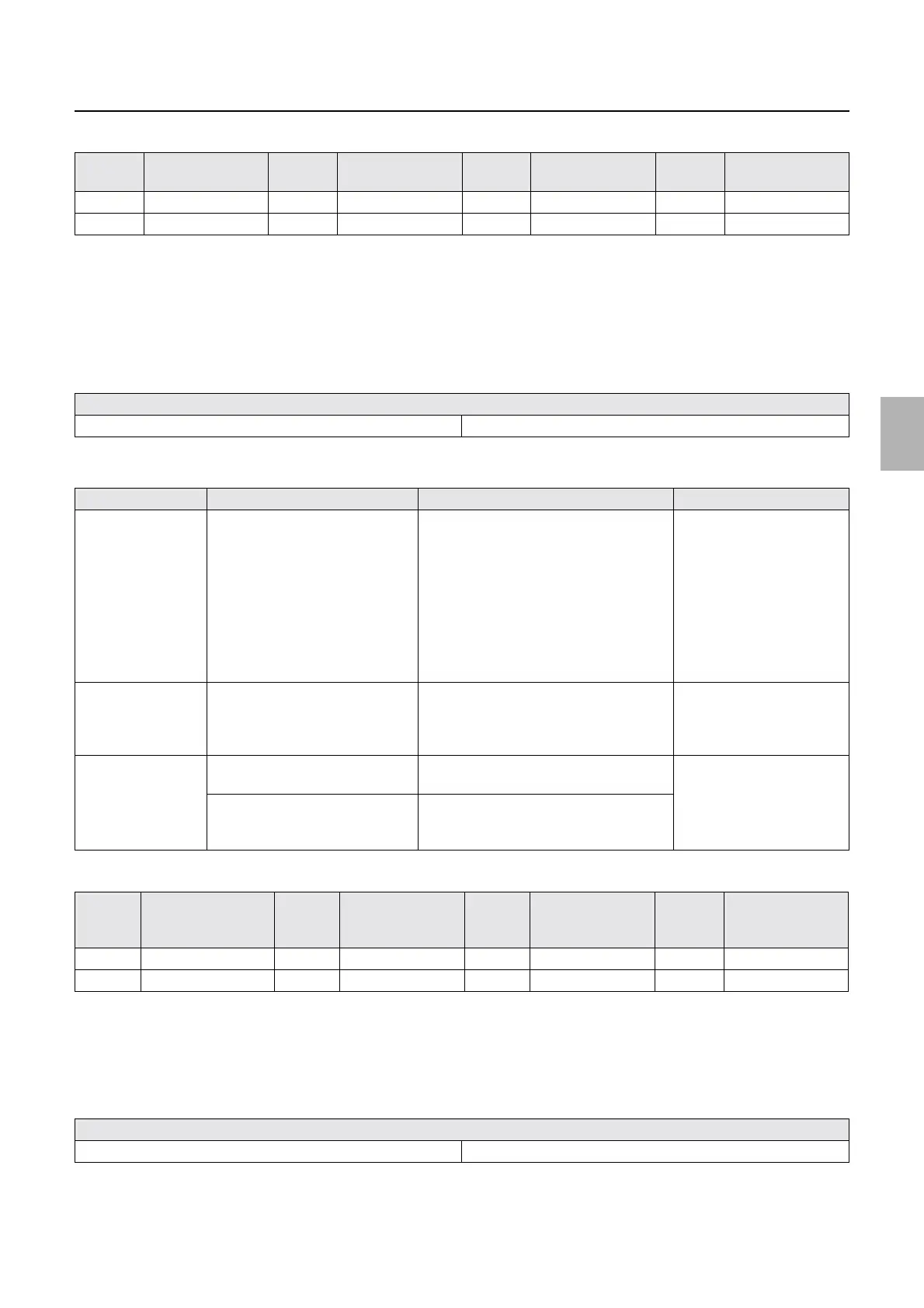
*1. The list below shows laser unit thermosensor resistance values by temperature.
*2. Check the status by turning on the Laser unit heater on Output Check.
☞35310
!
!!
! If the temperature of B laser thermosensor is not within the range from 46.7°C to
47.3°C.
1. Check if there is a wiring connection failure.
2. Make a diagnosis referring the displayed temperature on the B laser unit temperature sensor.
*1. The list below shows B laser thermosensor resistance values by temperature.
!
!!
! If the temperature of R laser thermosensor is not within the range from 46.7°C to
47.3°C.
1. Check if there is a wiring connection failure.
TEMPER
ATURE
Resistance TEMPER
ATURE
Resistance TEMPER
ATURE
Resistance TEMPER
ATURE
Resistance
523 kΩ to 25 kΩ 10 18 kΩ to 20 kΩ 15 14 kΩ to 16 kΩ 20 11 kΩ to 12 kΩ
25 9.2 kΩ to 9.8 kΩ 30 7.4 kΩ to 7.9 kΩ 35 6.0 kΩ to 6.4 kΩ
Wiring connection failure
Laser control PCB (J/P1504) ↔ laser unit Laser control PCB (J/P1532) ↔ laser unit
Checking point Checking content How to check Failure part
B laser temperature
control section
Peltier control voltage • If the voltage between pin 6 of J1532
and laser control PCB (GND) is less
than 24 V
• If the voltage between pin 5 of J1532
and laser control PCB (GND) is 0 V or
more and less than 0.8 V
• When heated: 0 V or more and
less than 0.8 V
• When it is off: 0 V
Laser unit (B laser
temperature control section)
B Laser
Thermosensor
*1
B laser thermosensor resistance
value
Remove J1504 and measure the resistance
value between Pin 8 (+) and 9(−). It is
normal if the resistance value is the same as
the value in the list below.
*1
Laser unit (B laser unit
thermosensor)
Laser control PCB B laser thermosensor standard
voltage
It is normal if the standard voltage between
Pin 8 (+) and 10 (−) of J1504 is 1 V.
Laser control PCB
B laser thermosensor measuring
voltage
It is normal if the voltage between Pin 9 (+)
and 10 (−) of J1504 is around 350 mV
under 28°C temperature.
TEMPE
RATUR
E
Resistance TEMPE
RATUR
E
Resistance TEMPE
RATUR
E
Resistance TEMPER
ATURE
Resistance
5 11.4 kΩ to 12.7 kΩ 10 9.2 kΩ to 10.3 kΩ 15 7.4 kΩ to 8.5 kΩ 20 6.0 kΩ to 7.0 kΩ
25 5.0 kΩ to 5.8 kΩ 30 4.1 kΩ to 4.8 kΩ 35 3.4 kΩ to 4.0 kΩ
Wiring connection failure
Laser control PCB (J/P1504) ↔ laser unit Laser control PCB (J/P1532) ↔ laser unit
Distributed by: minilablaser.com