6. Electrical parts
66200
2/3
66200
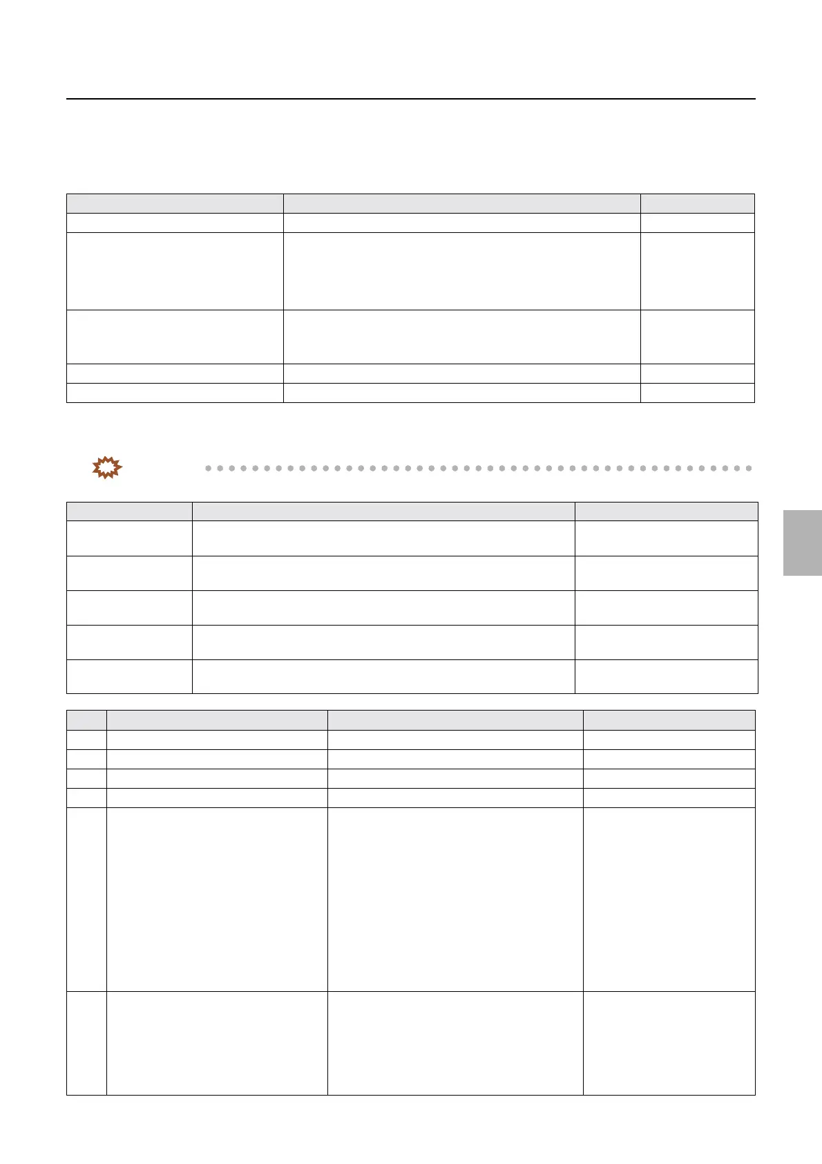
Explanation of PCBs (Processor section)
• On this PCB, the optical fiber cables are connected to the connectors J517 (IN) and J518 (OUT). Be sure to read the
Precautions for handling the optical fiber cable and LVDS cable, then work properly.
☞68100
!
!!
! Unused connector
!
!!
! Component parts table
IMPORTANT
• Although sometimes the test pins are unmounted, the test points can be used for the measurement.
Connector No. Purpose Remarks
P512 Digital flowmeter Option
P520 • [N] specification: unused
• [SM] specification: connecting to SM I/O PCB
• [J] specification: connecting to tablet replenishment driver PCB
• [F] specification: connecting to F replenishment I/O PCB
P521 • [N][SM] [J] specifications: unused
• [F] specification: connecting to the temperature and humidity
sensor
P526, P527, P528, P529, P530 • [F][N][SM][J] specifications: unused
P531, JP2 • [F][N][SM][J] specifications: unused
LED No. Purpose Status
LED1 DC+24 V input check On when the power supply is
turned on.
LED2 DC+5 V input check On when the power supply is
turned on.
LED3 DC+12 V input check On when the power supply is
turned on.
LED4 DC+5 V input check On when the power supply is
turned on.
LED5 DC12 V input check On when the power supply is
turned on.
TP Purpose When the normal value (# V) is not detected Symptom
TP1 Ground −−
TP2
*1
Unused −−
TP3
*1
Unused −−
TP4 Ground −−
TP5 DC24 V voltage measurement
• Order distinguish LED PCB, sensor
power supply, analog power supply
(DC12 V), colorimeter power supply
(DC12-1 V) and thermosensor analog
power supply (DC12 V)
• Connection failure between processor power
supply 1 and processor control PCB
• Failure in processor power supply 1 and
processor control PCB
• It shorted out between the processor control
PCB and order distinguish LED PCB
• The order distinguish LED
PCB does not emit light.
• The colorimeter does not
work.
• The order distinguish LED
PCB does not emit light.
• The temperatures of the
processing solution
temperature sensor and
dryer tthermosensor cannot
be adjusted.
TP6 DC5 V voltage measurement
• Power supply for digital circuits such
as FPGA, memory and CPU
• Connection failure between processor power
supply 1 and processor control PCB
• Failure in processor power supply 1 and
processor control PCB
• It shorted out between the processor control
PCB and each sensor.
•
☞No. 06901 ARCNET
communication error.
occurs.
Distributed by: minilablaser.com