Explanation of PCBs (Processor section)
1/3
6. Electrical parts
66200
66200
Explan ation of PCBs (Pr ocessor section )
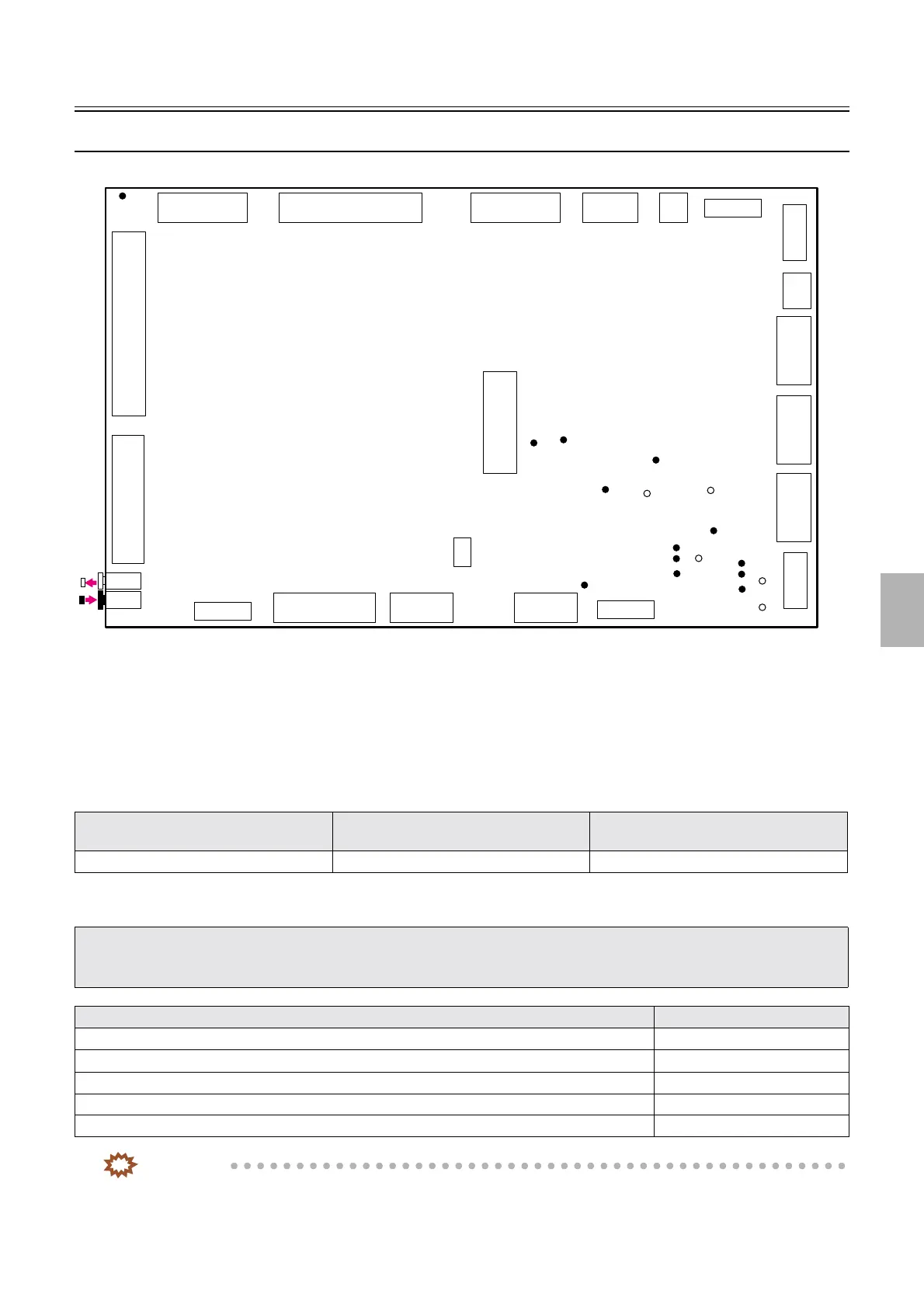
Processor control PCB (J391467)
!
!!
! Function
• Controls each electrical part of the processor section.
• Controls the Paper Sensor 1 and Paper Sensor 2 of the colorimeter unit.
• Communicates between the colorimeter and processor control PCB
!
!!
! Reference
!
!!
! Adjustments and precautions for PCB replacement
IMPORTANT
• Only for F specification, the following error messages may appear in a specific condition after initializing the data.
☞No. 05905[F], ☞No. 05906[F] , ☞ No. 05907[F]
Layout diagram Symptom due to the poor connection of
wiring
Symptoms of fuse blowout
☞63200 ☞4203 -
• When replacing a PCB, save the Memory data and Logdata of when a problem (error) occurs.
Press the Alt key and the Y key on the keyboard when the problem occurs.
☞31110
• Return the failed PCB with the Memory data and Logdata.
Explanation Reference
• Backup the system data. ☞35400
• Check the setting of the DIP switch. -
• Check the jumper connector. -
• Read the system program.
☞35600
• Load the system data.
☞35400
P530
P517
P518
TP1
TP5
TP6
TP8
TP13
LED3
P521P516P529P528P531
P522 P520 P519 P512P527 P523
P525
P526
P524
P515
P513
P514
P511
P510
TP7
LED1
LED2
TP9
LED5
LED4
TP11
TP3
TP10
TP2
TP4
JP2
TP12
G085261
Distributed by: minilablaser.com