I-26 F650 DIGITAL BAY CONTROLLER GEK-106310-AF
I.1 FACTORY DEFAULT SETTINGS APPENDIX I: FACTORY DEFAULT CONFIGURATION
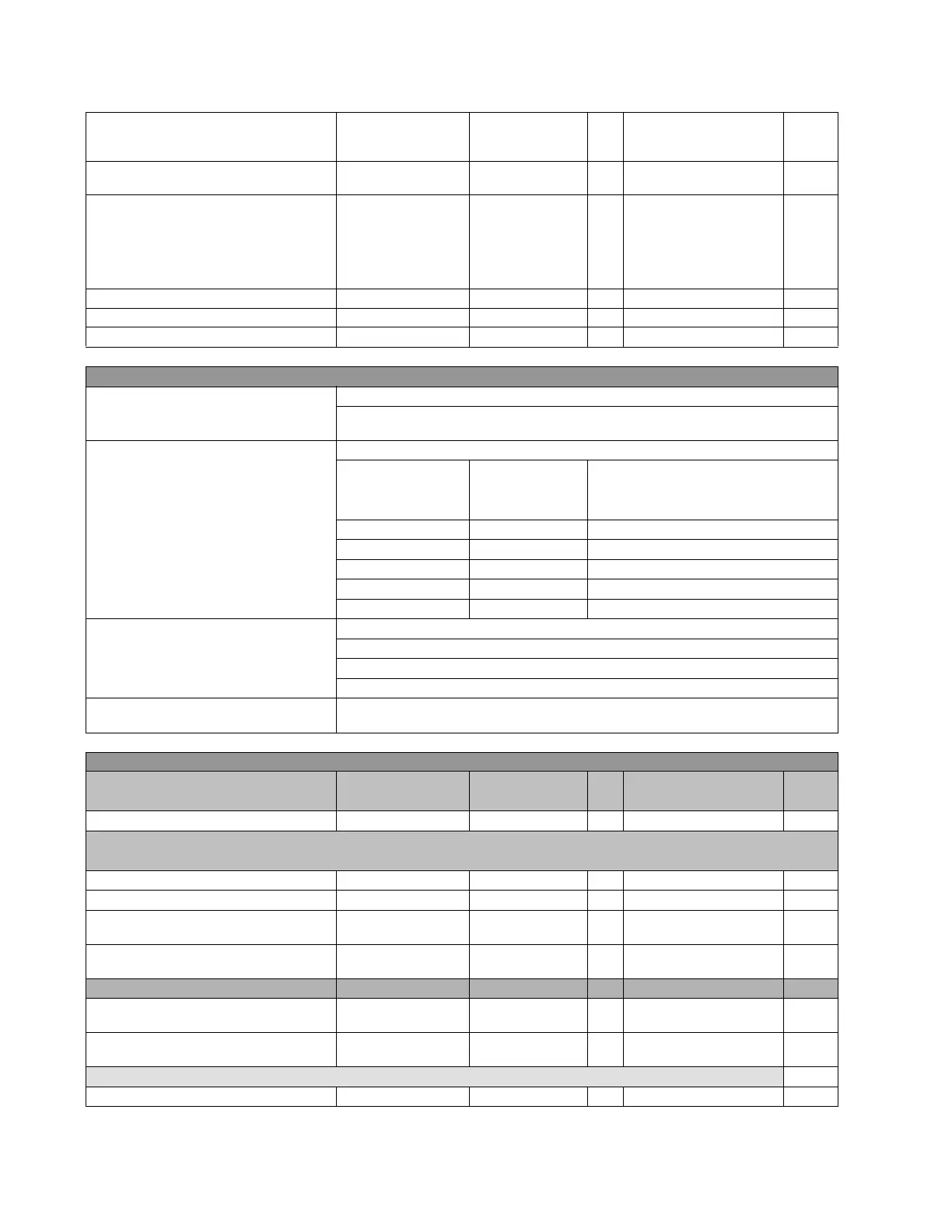
Output type Output Type_X_0Z NORMAL N/A [NORMAL,
PULSE,
LATCH]
Output pulse length Pulse Output
Ti
me_X_0Z
10000 1 ms [0 : 60000]
Analog Inputs Range Range_X_0Z NONE N/A [NONE,
-1 to 0mA,
0 to 1 mA,
-1 to 1 mA,
0 to 5 mA,
0 to 10 mA]
Minimum Value Min_Value_X_0Z 0.00 0.01 [ -9999.99 : 9999.99]
Maximum Value Max_Value_X_0Z 0.00 0.01 [ -9999.99 : 9999.99]
Snapshot event generation Snapshot Events ENABLED N/A [DISABLED – ENABLED]
Note 2: Description of X, Y and Z in input/output boards
X
F, G, H or J, the I/O board name, depending on the Relay model.
F and G are internal Relay boards, and H and J are additional boards available in CIO
modules (remote Bus CAN I/O module)
For the I/O board selection in the relay
mo
del:
I/O BOARD TYPE
ASSOCIATED DIGIT
ENERVISTA 650
SETUP BOARD
SETTINGS
BOARD TYPE
0 NONE None
1 16 INP+ 8 OUT
Mixed
2 8 INP +8 OUT +SUPV Supervision
4 32 INP 32 digital inputs
5 16 INP + 8 ANA 16 digital inputs + 8 analog inputs
CCY
Is the name used for inputs in I/O boards
Mixed, 16 d
igital inputs: CC1….CC16
Supervision: 8 d
igital inputs: CC1,..., CC8
32 INP: 32 digital inputs; CC1,...,CC32
0Z
Is the name used for the different outputs in I/O boards, 8 outputs available for any of the
two t
ypes of board (01,…., 08)
Setpoint > inputs/outputs > remote comms
Setting Description Name Default Value Step Range
User
Value
Remote comms selection Remote Comms NONE N/A [NONE – GSSE – GOOSE]
SETTING DESCRIPTION FOR GSSE
Remote comms selection Remote Comms GSSE N/A [NONE – GSSE – GOOSE]
Device Identification 650 ID F650 N/A
Hold time signal send by the transmiting
device
Hold Time 10000 1 ms [1000 : 60000]
Snapshot Events Generation
Snapshot Events
Rem
ote Out
DISABLED N/A [DISABLED – ENABLED]
Remote Device Description Remote Device X Remote Device X N/A
Bit Pair Selection Bit Pair X None N/A
[DNA-1 to DNA-32 –
UserS
t-1 to UserSt-64]
Default Value Selection Default Value X OFF N/A
[OFF – ON – LATEST OFF –
LA
TEST ON]
SETTING DESCRIPTION FOR GoOSE
Remote comms selection Remote Comms GOOSE N/A [NONE – GSSE – GOOSE]
 Loading...