CHAPTER 5: SETPOINTS 5.5 CONTROL ELEMENTS
GEK-106310-AF F650 DIGITAL BAY CONTROLLER 5-111
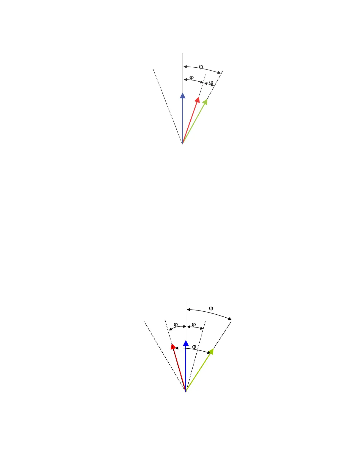
The Closing process using anticipative algorithm is described on the following figure:
Figure 5-25: Anticipative algorithm
Where:
V
ref
Referenced phasor (the one with lower frequency)
V
s
Actual voltage phasor (the one with lower frequency)
V’
s
Calculated voltage phasor, depending on the set breaker closing time (anticipative algorithm)
j 360º *TCB *Df = Calculated angle for phasor V’
s
TCB Breaker Closing time defined by setting
Df Frequency slip (mHz) between phasors
j
1
Angle difference set as maximum angle difference (Dj
set ,
Max Angle Difference)
j
2
= Angle difference between V
ref
and V
s.
The algorithm starts operating when j
2
equals two times the angle
set as maximum angle difference.
Closing permission is given when V’
s
is over V
ref
, which means that line and busbar voltages are in phase.
If the frequency slip is high, it is possible that as soon as the window defined by two times the maximum angle difference
(j
2
) is entered, the relay produces a closing permission output, if it is guaranteed that the projected phasor is within the limit
marked by the setting, as shown in the following figure. Besides, when the product of frequency slip and breaker close
time goes beyond this window, closing is not allowed.
Figure 5-26: High slip closing permission signal