CHAPTER 5: SETPOINTS 5.9 RELAY CONFIGURATION
GEK-106310-AF F650 DIGITAL BAY CONTROLLER 5-171
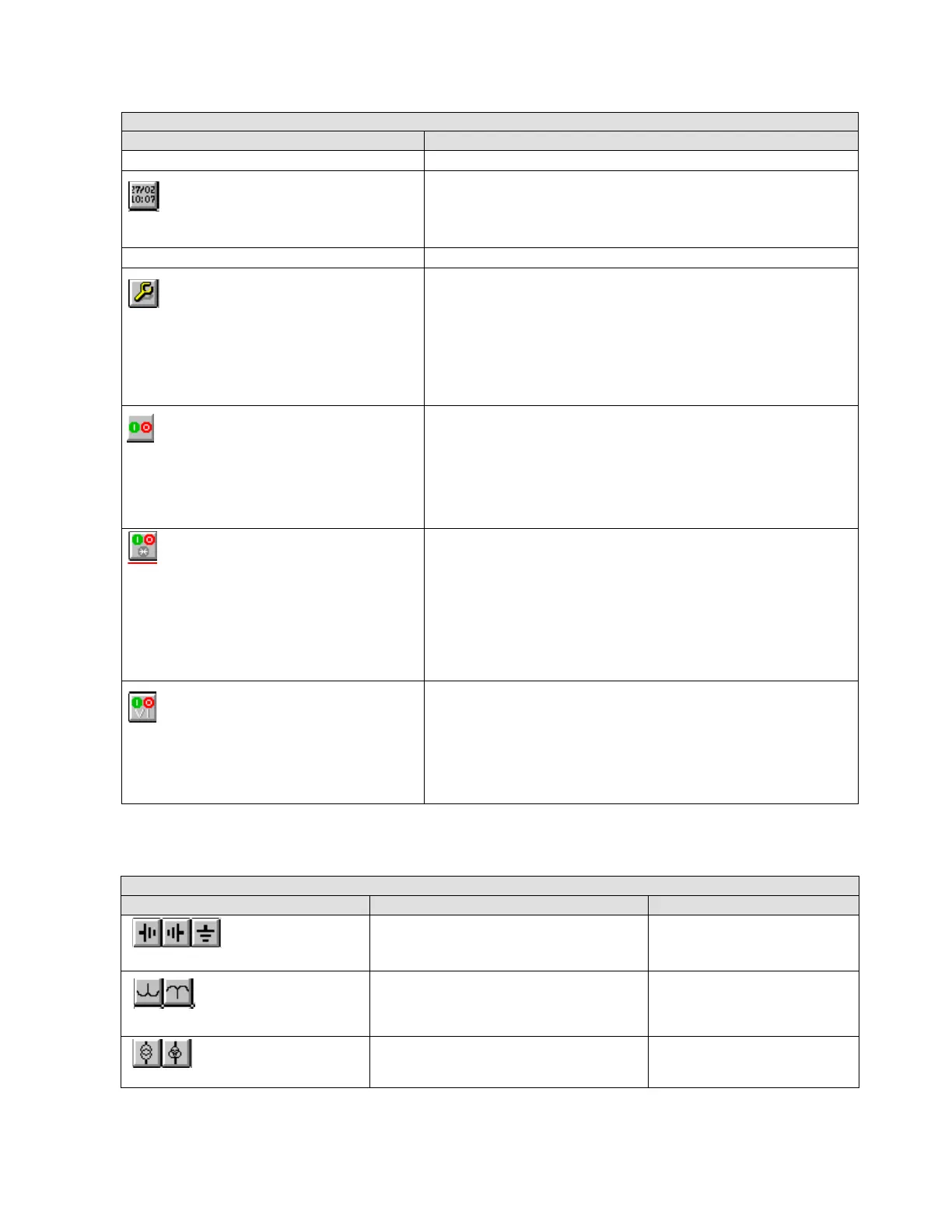
Table 5-95: GRAPHIC AND TEXT EDITION SYMBOLS
ACTIVE SYMBOLS
ICONS IN SCREEN DESCRIPTION
DATE AND TIME SYMBOL
Display the date and time provided by the device in the HMI.
OPERATIONS SYMBOL
Configure and execute operations on the graphic display.
This symbol can only be selected once the operations have been configured
in the Op
erations screen of the Relay Configuration menu. To select an
Operation, click the element and then the display. A window opens to select
the operation and the tab order. Once selected, a red border square is shown.
Place this square on the object to operate. When the object is selected on the
screen to execute this operation, the object on which it is located blinks. It is
possible to place several operations on the same object, for example to open
and close the breaker object.
Configure and execute operations with the front keys "I" and "O" on the
graphic d
isplay over an object selected.
To select the object, click the element and then the display. A window opens
t
o select the required operations "I" and "O" and the tab order. Once selected,
a blue border square is shown. Place this square on the object to operate.
When the object is selected on the screen to execute these operations, the
object on which it is located blinks. Press key "I" or "O" to execute the
configured operations.
Configure and execute operations with the front keys "I", "O" and "*" on the
graphic d
isplay over an object selected.
To select the object, click the element and then the display. A window opens
t
o select the required operations "I", "O" and "*" and the tab order. Once
selected, a green border square is shown. Place this square on the object to
operate. When the object is selected on the screen to execute these
operations, the object on which it is located blinks. Press key "I", "O" or "*" to
execute the configured operations.
After executing this kind of operation, information about the result of the
op
eration is displayed on the HMI..
Configure and execute virtual inputs with the frontal keys "I" and "O" on the
graphic d
isplay over an object selected.
To select the object, click the element and then the display. A window opens
t
o select the required virtual operations "I" and "O" and the tab order. Once
selected, a white border square is shown. Place this square on the object to
operate. When the object is selected on the screen to execute this virtual
inputs, the object on which it is located blinks. Press key "I" or "O" to set the
configured virtual inputs.
GRAPHIC AND TEXT EDITION SYMBOLS
ICONS IN SCREEN DESCRIPTION AVAILABILITY
Ground symbols in different positions. The first two are not available in the
N m
odel (IEC selection).
Voltage Transformers representation Only for standard model M.
Two and three winding voltage transformers
r
epresentation.
Only for N model (IEC selection)