5-178 F650 DIGITAL BAY CONTROLLER GEK-106310-AF
5.10 LOGIC CONFIGURATION (PLC EDITOR) CHAPTER 5: SETPOINTS
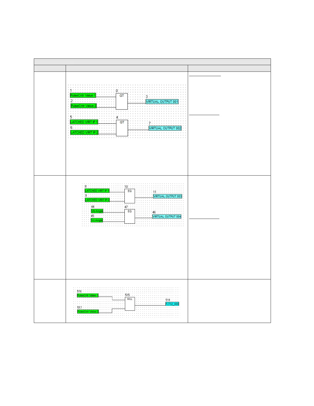
Example of analog operands in F650 logic configuration:
Table 5-99: Analog operands in F650
When this operand is used, Subtraction between two inputs is performed and result is stored into variable assigned to subtraction output.
ANALOG OPERANDS
OPERANDS example Description
GREATER THAN
Analog Variables:
1. If Pulse Cntr value 1 > Pulse Cntr value 2
then Virtual output is set to 1
2. If Pulse Cntr value 1 = Pulse Cntr value 2
then V
irtual output is set to 0
3. If Pulse Cntr value 1 < Pulse Cntr value 2
t
hen Virtual output is set to 0
Digital Variables:
1. If Latched Virtual input 1 =0 & Latched
Virtual input 2 =0 then Virtual output is
set to 0
2. If Latched Virtual input 1 =1 & Latched
V
irtual input 2 =1 then Virtual output is
set to 0
3. If Latched Virtual input 1 =1 & Latched
V
irtual input 2 =0 then Virtual output is
set to 1
4 If Latched Virtual input 1 =0 & Latched
V
irtual input 2 =1 then Virtual output is
set to 0
EQUAL TO Analog Variables:
4. If Vb Angle > Vc Angle then Virtual output
is
set to 0
5. If Vb Angle = Vc Angle then Virtual output
is set
to 1
6. If Vb Angle < Vc Angle then Virtual
output is set t
o 0
Digital Variables:
5. If Latched Virtual input 1 =0 & Latched
Virtual input 2 =0 then Virtual output is
set to 1
6. If Latched Virtual input 1 =1 & Latched
V
irtual input 2 =1 then Virtual output is
set to 1
7. If Latched Virtual input 1 =1 & Latched
V
irtual input 2 =0 then Virtual output is
set to 0
8. If Latched Virtual input 1 =0 & Latched
V
irtual input 2 =1 then Virtual output is
set to 0
MULTIPLIER Result of multiplication of both inputs is
st
ored into variable assigned to Multiplier
output