4200-900-01 Rev. K / February 2017 Return to Section Topics 3-41
Model 4200-SCS User’s Manual Section 3: Common Device Characterization Tests
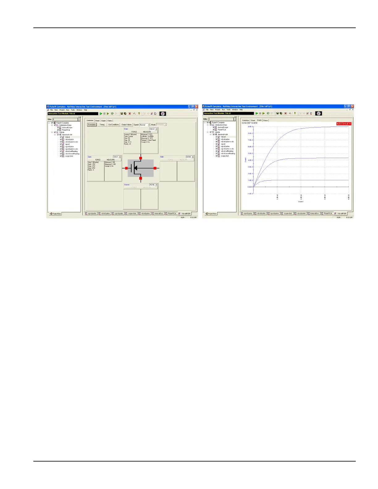
To run vds-id DC ITM:
1. Double-click the vds-id ITM in the project navigator (see Figure 3-36).
2. Click the green Run button. Three vds-id curves will be generated and displayed on the
graph.
Figure 3-39
Default definition and typical graph for vds-id
Running vds-id-pulse UTM
The default vds-id-pulse test uses (see Figure 3-40) the same drain voltage
settings as the DC vds-id. The vds-id-pulse does not have the automatic step
capability of the DC vds-id. There are two ways to generate a family of pulse IV
curves. The easier way is to use the vds-id-pulse-vs-DC (see Running vds-id-
pulse-vs-dc UTM below). If using the 8101-PIV test fixture, insert the metal can
(SD-210) DUT as shown in Figure 3-35.
To run the three gate voltages using single curve vds-id-pulse:
1. Ensure that the VdStart, VdStop, VdStep values match the values in the DC vds-id. To
sweep from a high to a low voltage, enter voltages so that vdstop < vdstart and use a
negative value for VdStep. If any values need to be modified, remember to press the Enter
key after typing in the value.
2.Set vgs to the first voltage. The default is 1.5 V. Make sure to press the Enter key after
typing in the value.
3. Click the green Run button.
4. After the test is finished, set vgs to the second voltage. The default is 2.0 V.
5. Click the yellow and green Append button.
6. After the test is finished, set vgs to the third voltage. The default is 2.5 V.
7. Click the yellow and green Append button.
8. To add or update the DC results on the pulse Graph, perform the procedure for Comparing
DC and pulse results.
 Loading...
