3-68 Return to Section Topics 4200-900-01 Rev. K / February 2017
Section 3: Common Device Characterization Tests Model 4200-SCS User’s Manual
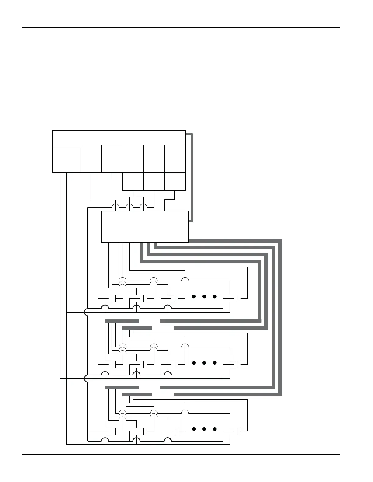
How to perform reliability (stress-measure) tests on my device
Connecting devices for stress / measure cycling
Devices that are stress / measure cycled in parallel are connected through a
switch matrix. Figure 3-49 shows an example of such connections for an HCI
evaluation.
Figure 3-49
Stress / measure wiring example
4210-
SMU
5
Ground
Unit
D
uring Characterization of Each Transistor
Vds = SMU3
Vgs = SMU1
Vbb = SMU2
Vss = Ground Unit
During Stress
SMU1 = Common Gate
SMU2 = Common Substrate
SMU3 = All Drains at 3.5 Volts
SMU4 = All Drains at 4.0 Volts
SMU5 = All Drains at 4.5 Volts
4200-SCS
Switch Matrix
8 ´ 36 (Three cards in
Mainframe)
4
210-
SMU
4
4210-
SMU
3
4210-
SMU
2
4210-
SMU
1
Preamp Preamp Preamp
GPIB
S
e
n
s
e
F
o
r
c
e
L
o
w
1 23 6
1 23 6
1 23 6
6 Cables
6 Cables
6 Cables
6 Cables

 Loading...