4200-900-01 Rev. K / February 2017 Return to Section Topics 3-87
Model 4200-SCS User’s Manual Section 3: Common Device Characterization Tests
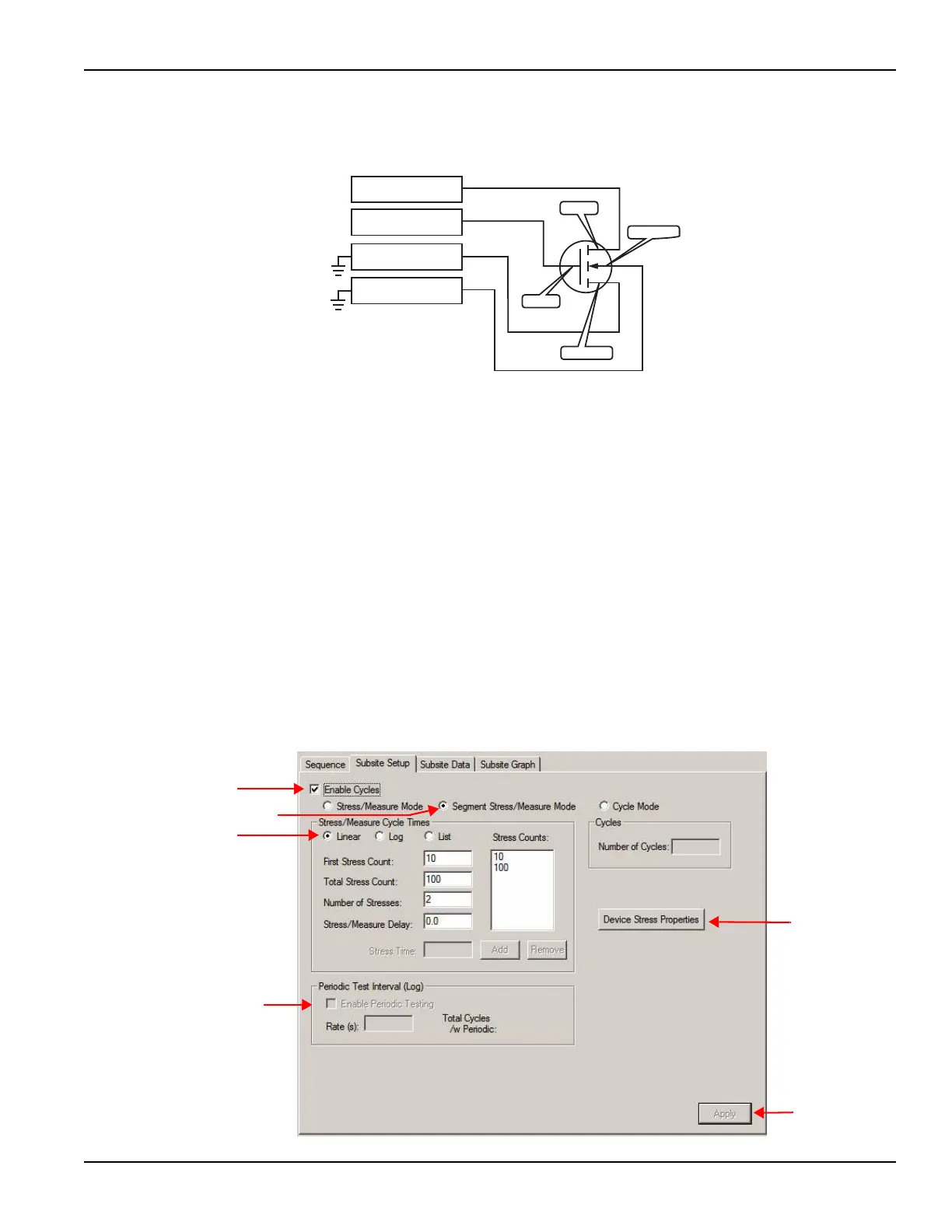
Figure 3-68
Segment stressing: Stress phase example
Segment Stress / Measure Mode configuration
The Segment Stress / Measure Mode is configured from the subsite setup tab.
After double-checking the name of the subsite plan in the project navigator, select
the subsite setup tab (see Figure 3-69).
For Segment ARB
®
stressing, the waveform period is the fundamental unit of time
for stressing. In the subsite setup tab, stress counts specify the number of times
the Segment ARB waveform stresses the device. For example, assume the stress
count is 3, and the waveform period is 4 seconds. For that stress cycle, the
Segment ARB waveform stresses the device 3 times for a total stress time of 12 s.
Configure stress counts
To configure the stress counts for the Segment / Stress Measure Mode:
Figure 3-69
Segment Stress / Measure Mode: Subsite Setup
Pulse Card
4200-SMU (1)
4200-SMU (2)
Ch 1
Signal
Ground*
SARB Waveform
Signal
Ground*
0V
0V
* Setting a SMU to 0V
connects the device
pin to signal ground.
Pulse Card
Ch 2
SARB Waveform
Source
Drain
Substrate
Gate

 Loading...