1-18 Return to Section Topics 4200-900-01 Rev. K / February 2017
Section 1: Getting Started Model 4200-SCS User’s Manual
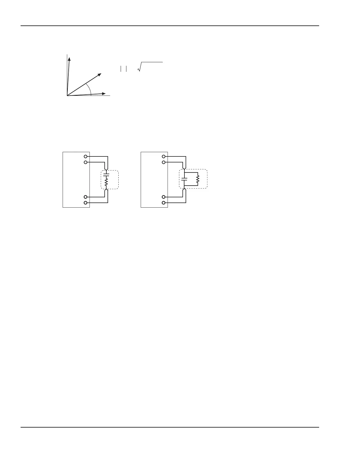
Figure 1-13
Vector diagram for impedance (Z)
The simplified model of a DUT is a resistor and a capacitor. As shown in Figure 1-14, the
4210-CVU can measure the DUT as a series configuration of the resistor-capacitor (RC), or as a
parallel RC configuration.
Figure 1-14
Measure models (simplified)
Test signal
The test signal can be set for the following frequencies:
• 1 kHz through 10 kHz in 1 kHz increments
• 10 kHz through 100 kHz in 10 kHz increments
• 100 kHz through 1 MHz in 100 kHz increments
• 1 MHz through 10 MHz in 1 MHz increments
The AC signal output level can be set from 10 mV RMS to 100 mV RMS (1 mV resolution). The
output impedance is 100 Ω (typical).
There are three current measurement ranges available to measure current: 1 µA, 30 µA or 1 mA.
With auto range selected, range selection will be performed automatically.
DC bias function and sweep characteristics
The AC test signal can be biased with a static DC level (-30 V to +30 V), or a voltage sweep (up or
down).
ZR
2
X
2
+=
ZRjX+=
θ arc
X
R
----
tan=
RZ θcos=
XZθsin=
Y
1
Z
---= GjB+()=
Z = Impedance
θ = Phase Angle
R = Resistance
X = Reactance
Y = Admittance
G = Conductance
HCUR
HPOT
LPOT
LCUR
4200-CVU
Cs
Rs
Series RC Configuration
HCUR
HPOT
LPOT
LCUR
Cp
Rp
Parallel RC Configuration
DUT
DUT
4200-CVU