4200-900-01 Rev. K / February 2017 Return to Section Topics 1-29
Model 4200-SCS User’s Manual Section 1: Getting Started
NOTE Specifications are subject to change; for the latest specifications, visit
www.ztecinstruments.com.
Scope card settings
The following information summarizes the most frequently used settings for the scope. For
detailed information about all scope settings.
Keithley Instruments user modules are used to control waveform acquisition operations of the
scope. New user modules can be created, or existing user modules can be modified (see the
Reference Manual, Keithley Interactive Test Environment (KITE), page 6-1, for details). For more
information about ZTEC, refer to the Model 4200-SCS Complete Reference, ZTEC User’s Manual.
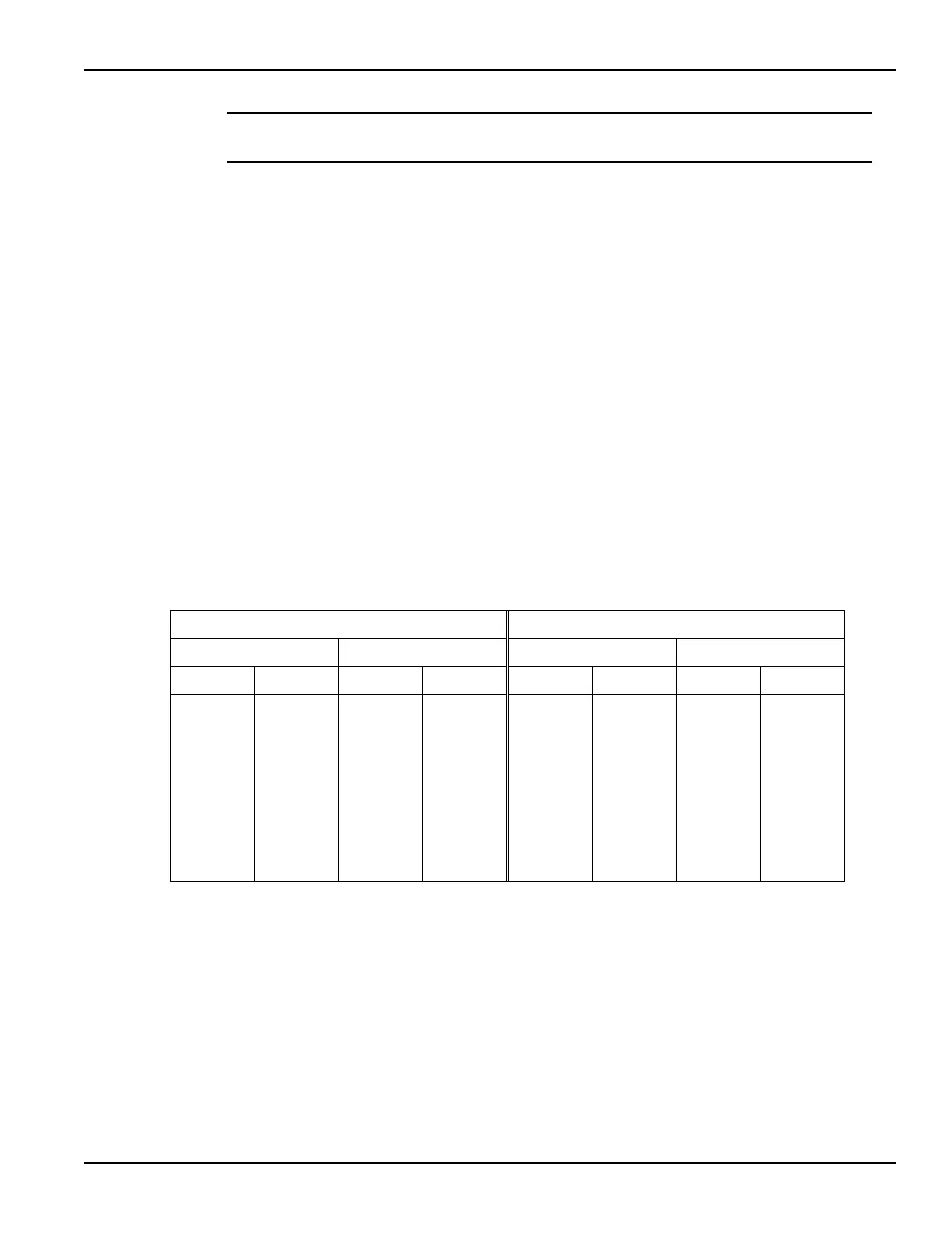
Input impedance, input voltage range, and input voltage offset
Table 1-3 lists the input impedances, voltage ranges, and voltage offsets that can be set for each
input channel. As shown in the table, the setting for each of these parameters depends on the
settings of the other two parameters. For example, to select 50 Ω input impedance, range must
already be set to one of the eight ranges listed in the table for 50 Ω, and voltage offset must not be
set greater than ±10 V.
To avoid settings conflicts, first set voltage offset to 0 V, and then select the 10 V range. These
settings are compatible with both impedance settings. Now you can set impedance, range, and
then offset, in that order.
Input coupling
Input coupling, which is used to pass or block the DC component of an input signal, can be set to
AC or DC:
• DC coupling passes all frequencies
• AC coupling blocks low frequencies; with high-input impedance (1 M Ω) selected, AC
coupling attenuates frequencies below 10 Hz; with low input impedance (50 Ω) selected, AC
coupling attenuates frequencies below 200 kHz
Table 1-3
Scope impedance, range, and offset settings
1M Ohm impedance 50 Ohm impedance
Model 4200-SCP2HR Model 4200-SCP2 Model 4200-SCP2HR Model 4200-SCP2
Range Offset Range Offset Range Offset Range Offset
50 V pp 0 V 100 V pp ±50 V 10 V pp 0 V 10 V pp ±5 V
25 V pp ±12.5 V 50 V pp ±25 V 5 V pp ±2.5 V 5 V pp ±2.5 V
10 V pp ±5 V 20 V pp ±10 V 2 V pp ±1 V 2 V pp ±1 V
5 V pp ±5 V 10 V pp ±5 V 1 V pp ±1 V 1 V pp ±0.5 V
2.5 V pp ±5 V 5 V pp ±2.5 V 0.5 V pp ±1 V 0.5 V pp ±0.25 V
1.25 V pp ±5 V 2.5 V pp ±1.25 V 0.25 V pp ±1 V 0.25 V pp ±0.125 V
0.5 V pp ±5 V 1 V pp ±0.5 V 0.1 V pp ±1 V 0.1 V pp ±0.05 V
0.25 V pp ±5 V 0.5 V pp ±0.25 V 0.05 V pp ±1 V 0.05 V pp ±0.025 V
——0.2 V pp±0.1 V ————
——0.1 V pp±0.05 V————

 Loading...