4200-900-01 Rev. K / February 2017 Return to Section Topics 3-21
Model 4200-SCS User’s Manual Section 3: Common Device Characterization Tests
CVU ITM examples
CVU Voltage Bias
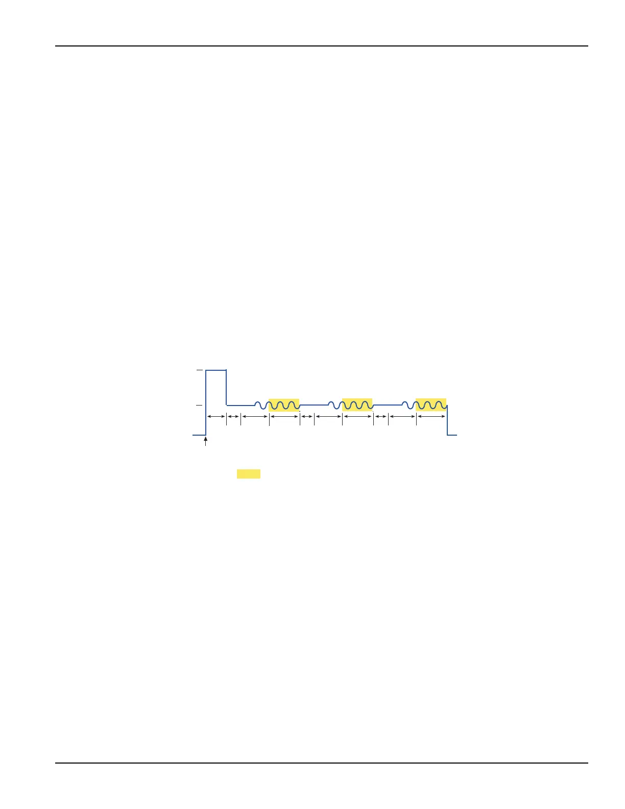
Figure 3-12 shows an example of a FFMO window with CVU Voltage Bias
selected as the forcing function to measure Cp-Gp. The Sampling test mode must
be selected for this test (see Figure 3-11).
When this test is run (see Figure 3-16), the following force-measure sequence
occurs:
1. The DC source goes to the PreSoak voltage of 5 V for the hold time.
2. The DC source goes to the DC bias voltage of 1 V.
3. After the built-in system delay and Interval, the 4210-CVU makes a measurement. The AC
test signal is applied just before the start of the measurement. AC drive is turned off after the
measurement is completed.
4. Step 3 is repeated for every sample.
The number of samples (measurements), interval between each measurement,
hold time and output disable are set from the ITM timing window for sampling.
Figure 3-16
CVU Voltage Bias output
HT
0V
1V
Frequency = 100kHz
AC Voltage = 15mVRMS
Meas
Meas
Meas
Bias
HT = Hold Time
SD = Built-In System Delay
Int = Programmed Interval
Meas = Measure Time
Disable outputs
at completion
enabled
Run
Test
5V
PreSoak
Int
SD
Int
SD
Int
SD

 Loading...