3-108 Return to Section Topics 4200-900-01 Rev. K / February 2017
Section 3: Common Device Characterization Tests Model 4200-SCS User’s Manual
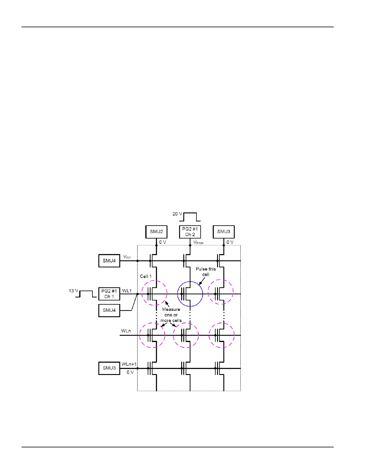
Disturbed cell testing – The outputs for the PG2s are turned off and their output
relays are opened. SMU1 and SMU2 are then used to perform a DC Vg-Vd sweep
on Cell 1 to determine V
T
.
Using a switch matrix
A limitation of the no-switch, direct connect test configuration shown in Figure
3-91 is that only three devices can be measured. The test would have to be
manually reconfigured or re-cabled to test other devices.
Without a switch matrix, the number of adjacent cells that can be measured is
limited. Therefore, it is recommended that a switch matrix be used for disturb
testing, as shown in Figure 3-97.
Using a switch matrix allows the flexibility of routing pulse and DC signals without
having to make connection changes. Also, this type of structure uses a multi-pin
probe card, which provides an additional opportunity for mapping test resources
to DUT pins. For example, a SMU can be shared across multiple device terminals
where the required voltage is the same.
Figure 3-91
Disturb testing – configuration to test a single device

 Loading...