2-16 Return to Section Topics 4200-900-01 Rev. K / February 2017
Section 2: Model 4200-SCS Software Environment Model 4200-SCS User’s Manual
Understanding pulse mode
To avoid device overheating in some tests, voltages or currents can be applied to a device only for
brief periods at widely spaced intervals. For sweep (linear, log, and list) and bias forcing functions,
a SMU can be set to provide pulse output.
With pulse mode enabled, the following pulse parameters can be set:
•On Time
• Off Time
• Base Voltage (or Base Current)
The base is the level the SMU goes to between sweep points. Pulse “on” and “off” times determine
pulse period and pulse width as follows:
• Pulse period = On Time + Off Time + cumulative measure time (if set to measure)
• Pulse width = On Time
Pulse mode can be selected only when source and measure ranges are fixed. Pulse mode is
disabled if the source or measure range is set to AUTO.
Pulse “on” and “off” times can be set from 5 ms to 10 s. The base voltage (or current) that can be
set is dependent upon the present source range.
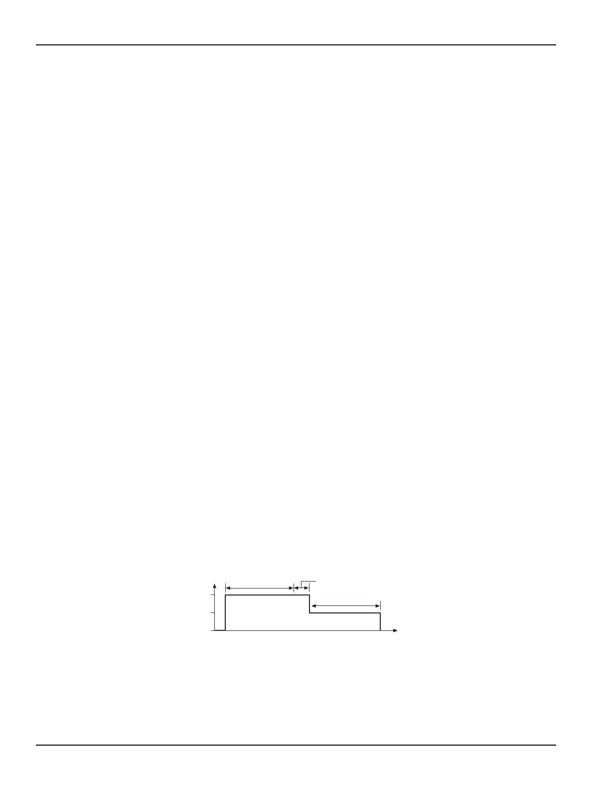
An example pulse output for the voltage bias forcing function is shown in Figure 2-7. Pulse output
goes to the specified pulse level during the pulse “on” time. If the SMU is set to measure, the
measurement will occur after the “on” time expires and before the transition to the “off” time level.
This effectively increases the “on” time by the amount of time required to make the measurement.
Minimize this extra time by choosing “custom” in the timing tab and setting delay and filter factor to
0, and A / D Integration factor to 0.01. This is the fastest (but least accurate) measurement timing
scheme. If not set to measure, the output will transition from “on” to “off.”
During pulse “off” time, the pulse output returns to the specified base voltage level. After the “off”
time expires, the output returns to 0 V.
For a sweep forcing function, pulse output steps to the sweep step levels during the pulse “on”
times. During the “off” times, pulse output returns to the specified base voltage (or base current)
level. if set to measure, the measurement will occur after each “on” time period expires and before
the pulse transitions to the “off” time level.
The voltage sweep in Figure 2-8 is a single sweep. If dual sweep is enabled, the test will continue
by going back to the stop level and then step down to the start level. For details, see
Understanding dual sweep, on page 2-15.
Figure 2-7
Pulse mode example: Voltage bias; 2V level, 1V base
0V
Base Voltage 1V
Level 2V
Off Time
On Time
Cumulative Measurement Time
Time