3-94 Return to Section Topics 4200-900-01 Rev. K / February 2017
Section 3: Common Device Characterization Tests Model 4200-SCS User’s Manual
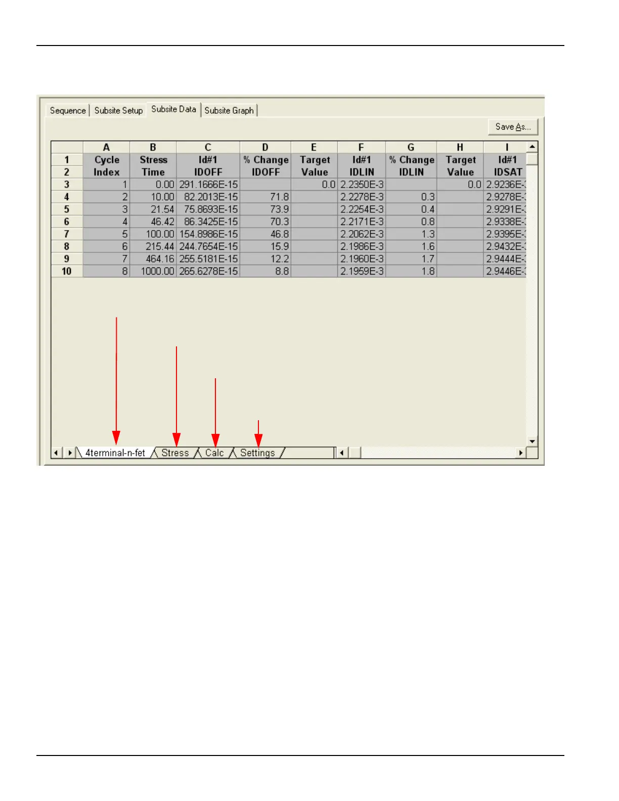
Figure 3-74
Subsite Data sheet: Stress / Measure Mode
Settings window
The Settings window displays information about the subsite cycling setup. The
Settings window is displayed by clicking the Settings tab at the bottom of Subsite
Setup tab (see Figures 3-73 and 3-74).
The Settings window for the Cycle Mode is shown in Figure 3-75. It provides basic
information on the subsite cycling setup and lists the Output Values for each
device and test. The Settings window for the Stress / Measure Mode is shown in
Figure 3-76. It is similar to the Settings window for the Cycle Mode and includes
information on Targets. For each enabled Target, the Target Value is listed. After
subsite cycling, it also indicates if Targets have been reached.
The above subsite data is for device 4terminal-n-fet. For a multi-device
Subsite Plan, there would be a separate tab for each device. The data for
other devices are displayed by clicking the corresponding label.
Clicking this tab displays any enabled stress
measurements. See Figure 3-66 for details.
Clicking this tab displays the Calc sheet. It is the
same as the Calc sheet for an ITM and UTM.
Clicking this tab displays information about the
subsite cycling setup, including Output Values and
Target evaluation. See Figure 3-76 for details.

 Loading...