3-30 Return to Section Topics 4200-900-01 Rev. K / February 2017
Section 3: Common Device Characterization Tests Model 4200-SCS User’s Manual
have been configured for testing leading edge, lower-power CMOS devices.
These tests, as well as initialization steps for scope auto-calibration and cable
compensation, are included in a single 4200-SCS test project,
Pulse-IV-Complete.
There is another Pulse IV test project, Demo-PulseIV. This demo project is a
subset of PulseIVComplete and is intended for demonstrating the Pulse IV
capabilities using a packaged demonstration DUT.
NOTE The user test modules (UTMs) used for Pulse IV tests are described in the following
paragraphs. These UTMs control all instrumentation for these applications. The pulse
generator and scope cards can also be used as stand-alone instruments. Reference
manual, Pulse Source-Measure Concepts, page 11-1 explains front panel operation
and provides remote programming information for individual control of the pulse
generator and scope. For remote programming, the pulse generator card uses
LPTLib functions, while the scope card uses kiscopeulib UTMs.
4200-PIV-A test connections
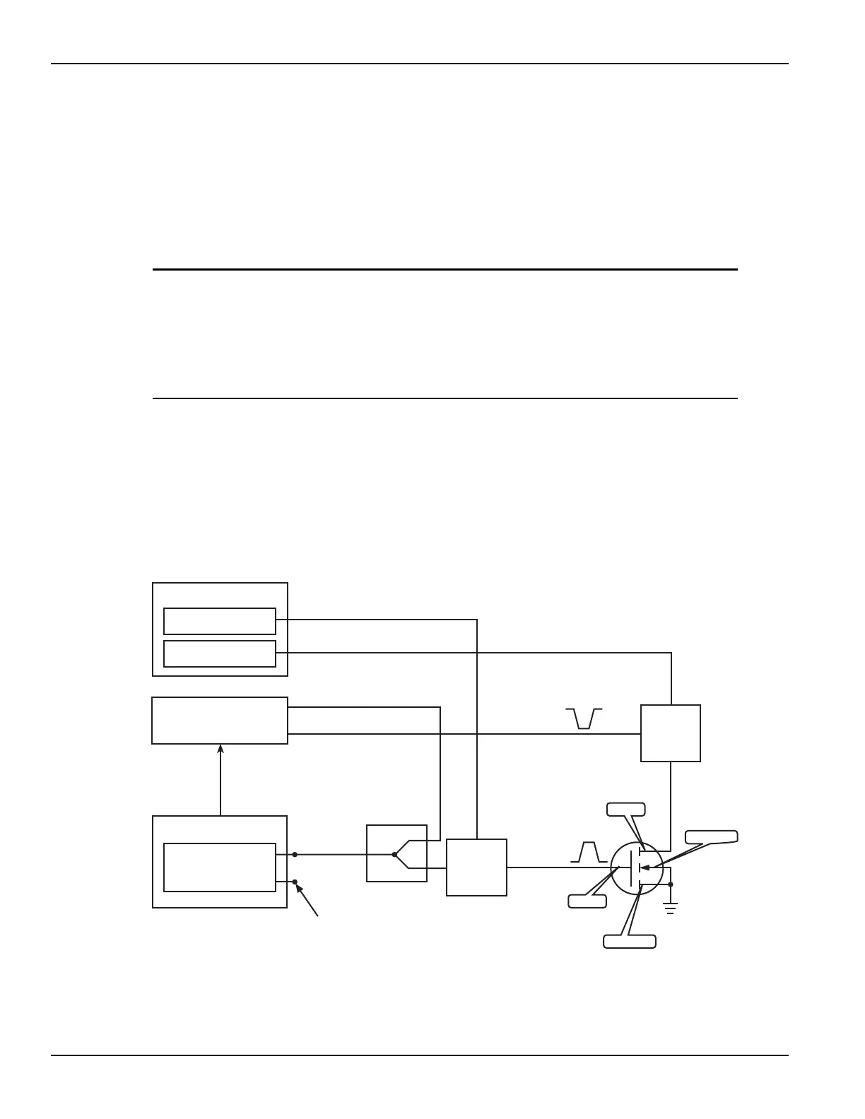
The block diagram for PIV-A testing is shown in Figure 3-25, and the hardware
connections are shown in Figure 3-26. A side view of the scope card is provided in
Figure 3-27 to show the adapters.
Figure 3-25
Pulse IV—hardware setup block diagram
Supplied interconnect parts
The interconnect parts listed in Table 3-2 are supplied with the PIV-A package.
4200-SMU (1)
4200-SMU (2)
4200-SCP2
4205-PG2
DC Bias and Measure
Scope
Pulse Generator
4205-RBT
(1)
4205-RBT
(2)
V
g
Channel 1
Channel 1
Output
V
DD
Trigger
AC+DC
Output
V
d
S
1
2
Channel 2
AC+DC
Output
Channel 2
(No Connection)
Source
Drain
Substrate
Gate
3-port
power
divider
NOTE The AC signal component to
4205-RBT (2) is required for
pulse V
d
(I
d
) measurement.

 Loading...