4-38 Return to Section Topics 4200-900-01 Rev. K / February 2017
Section 4: How to Control Other Instruments with the Model 4200-SCS Model 4200-SCS User Manual
Connections
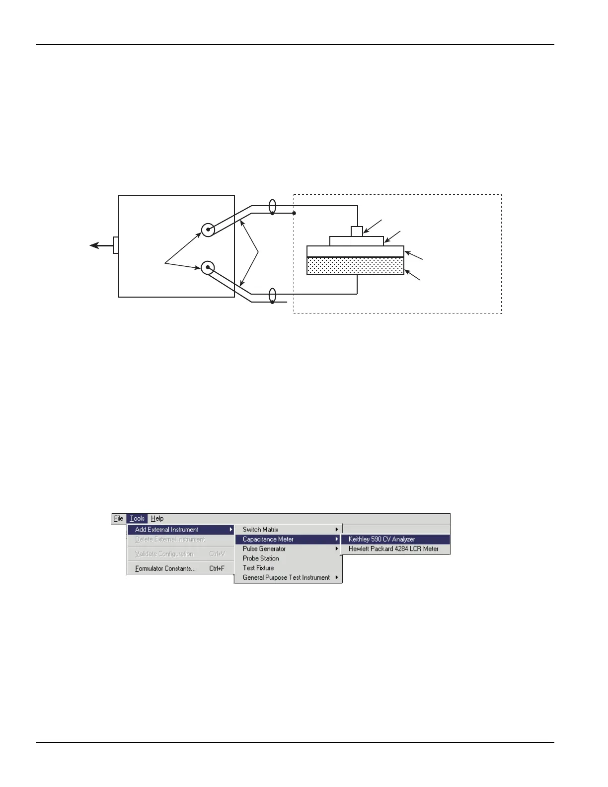
Connection details for the Model 590 CV Analyzer are provided in the Reference Manual,
Appendix C, Using a Keithley Instruments Model 590 CV Analyzer. The INPUT and OUTPUT
connectors of the 590 are connected to the capacitor using 4801 (RG-58) BNC cables. The 590 is
controlled by the 4200-SCS through the GPIB bus. Use a 7007 GPIB cable to connect the 590 to
the 4200-SCS. Figure 4-58 provides an illustration of these connections.
Figure 4-58
Keithley Model 590 CV Analyzer DUT connections
KCON setup
For this tutorial, the 590 CV Analyzer must be included in the 4200-SCS system configuration.
KCON is used to add external equipment to the test system. For details about KCON, refer to the
Reference Manual, Keithley CONfiguration Utility (KCON), Section 7.
To add the 590 to the system configuration using KCON:
1. Start KCON. Double-click the KCON icon or use the Start menu, Start > Programs >
Keithley > KCON.
2. Add the Keithley Instruments Model 590 CV Analyzer to the system configuration using the
KCON Tools menu as illustrated in Figure 4-59.
Figure 4-59
Adding a 590 CV Analyzer to the system configuration
3. Set the GPIB address for the 590 by selecting the KI 590 CV Analyzer - CMTR1 in the
configuration navigator and entering the appropriate GPIB address on the Properties &
Connections tab. This is illustrated in Figure 4-60.
Metal/polysilicon
Gate oxide
Silicon substrate
590 CV Analyzer
INPUT
OUTPUT
BNC
connectors
Wafer
BNC
cables
Faraday Shield
GPIB
To the
4200-SCS
Probe station
chuck

 Loading...