4200-900-01 Rev. K / February 2017 Return to Section Topics 1-23
Model 4200-SCS User’s Manual Section 1: Getting Started
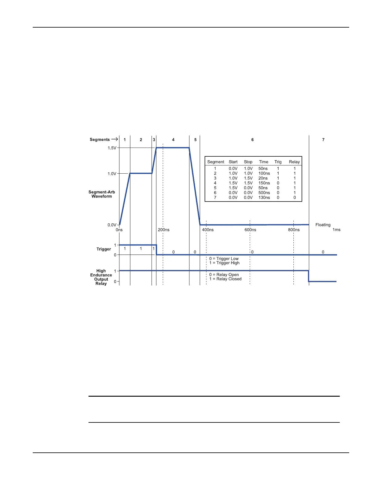
Segment ARB waveform
Each channel of a pulse card can be configured to output its own unique Segment ARB
®
waveform. A Segment ARB waveform is composed of user-defined line segments (up to 1024 for
the 4205-PG2 or 2048 for the 4220-PGU and 4225-PMU). Each segment can have a unique time
interval, start value, stop value, output trigger level (TTL high or low) and output relay state (open
or closed).
Figure 1-21 shows an example of a Segment ARB waveform that contains seven segments. It also
shows the programmed trigger levels and open/closed states for the output relay.
Figure 1-21
Segment ARB waveform example
Start, stop, and time restrictions:
• The start level of the first segment and the stop level of the last segment must be the same.
In Figure 1-21, segment 1 start and segment 7 stop are both set for 0.0 V.
• The stop level for a segment must be the same as the start level for the next segment. In
Figure 1-21, the stop level for Segment 1 is 1.0 V, as is the start level for Segment 2 (no
discontinuities are allowed).
• The minimum time per segment is 20 ns, with increments of 10 ns.
Trigger levels: The segment trigger levels are available at the TRIGGER OUT connector. When
set high (1), a TTL high level will be present at TRIGGER OUT during that time
interval. When set low (0), the trigger goes low for that segment. In Figure 1-21,
trigger is set high for the first three segments, and low for the rest of the segments.
NOTE If both channels of a pulse card are being used, the segment trigger levels for
CHANNEL 1 will be seen at the TRIGGER OUT connector. The trigger levels for
CHANNEL 2 are ignored.
111 1 1 1
0