3-50 Return to Section Topics 4200-900-01 Rev. K / February 2017
Section 3: Common Device Characterization Tests Model 4200-SCS User’s Manual
cal_pulseiv
Description The cal_pulseiv module is used to perform a cable compensation routine for the
4200-PIV package. This routine permits the system to compensate for losses in
the cabling from the 4200 to the connection to the DUT. Use this routine during
initial system setup and whenever changes are made in any part of the
interconnect (cables, 4200-RBTs, probe manipulators or pins).
There are two main steps to this procedure:
• Open cal: The gate signal is measured with no connection to the DUT.
• Through cal: The drain signal is measured while making contact on a Through
structure (or by shorting the two 4200-RBTs, AC+DC outputs with an
appropriate cable, or adapter).
The factors generated by this routine are used during any testing where the 4200-
RBTs are used (vdsid_pulse, vgsid_pulse). Make sure to set the appropriate values
for the cal_pulseiv parameters in Table 3-4. Table 3-5 and Table 3-6 contain outputs
and return values, respectively.
Connection The source and body (well) of the DUT must be shorted together and connected to
the common low (outer shield) of the SMA cables on the AC+DC output of the
RBTs. The RBT connected to GateSMU (with the Power Divider) should be
connected to the gate. The RBT connected to DrainSMU should be connected to
the drain. For detailed connection information, refer to the PIV-A interconnect
assembly procedure on page 3-35.
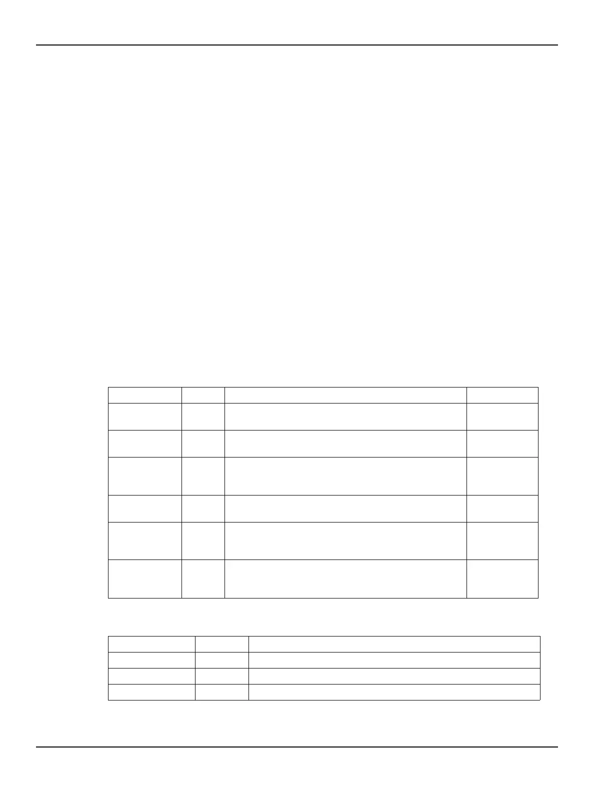
Table 3-4
Inputs for cal_pulseiv
Input Type Description Default
VPUID char * The instrument ID. This should be set to VPU1 for 4200
systems with the 4200-PIV package.
VPUID
GateSMU char * The SMU used for the Gate. This can be SMU1 up to the
maximum number of SmUs in the system.
GateSMU
DrainSMU char * The SMU used for the Drain. This can be SMU1 up to the
maximum number of SMUs in the system. This SMU
applies the DC bias to the DUT drain during the sweep.
DrainSMU
vRange int The pulse generator card voltage source range to be
calibrated (V). Valid values are: 5, 20.
5
PulsePeriod double The pulse period for the Vgs pulse. The period can be set
from 40 us to 1 s (10 ns resolution). The period must be set
so that the Duty Cycle (DC) is no more than 0.1%.
100 e-6
Vs_Size
Vm1_size
Vm2_size
int Set to a value that is at least equal to the number of steps
in the sweep and all three must be the same value.
100
100
100
Table 3-5
Outputs for cal_pulseiv
Output Type Description
Vs double * The pulse source value (V).
Vm1 double * The measured voltage from channel 1 of the scope card.
Vm2 double * The measured voltage from channel 2 of the scope card.
Note: These outputs are included for compatibility with older setups. They no longer return any information.

 Loading...