4200-900-01 Rev. K / February 2017 Return to Section Topics 3-139
Model 4200-SCS User’s Manual Section 3: Common Device Characterization Tests
described above, but adds support for an external Keithley switch matrix.
Example results for the Endurance tests are shown in Figure 3-113 and Figure
3-90.
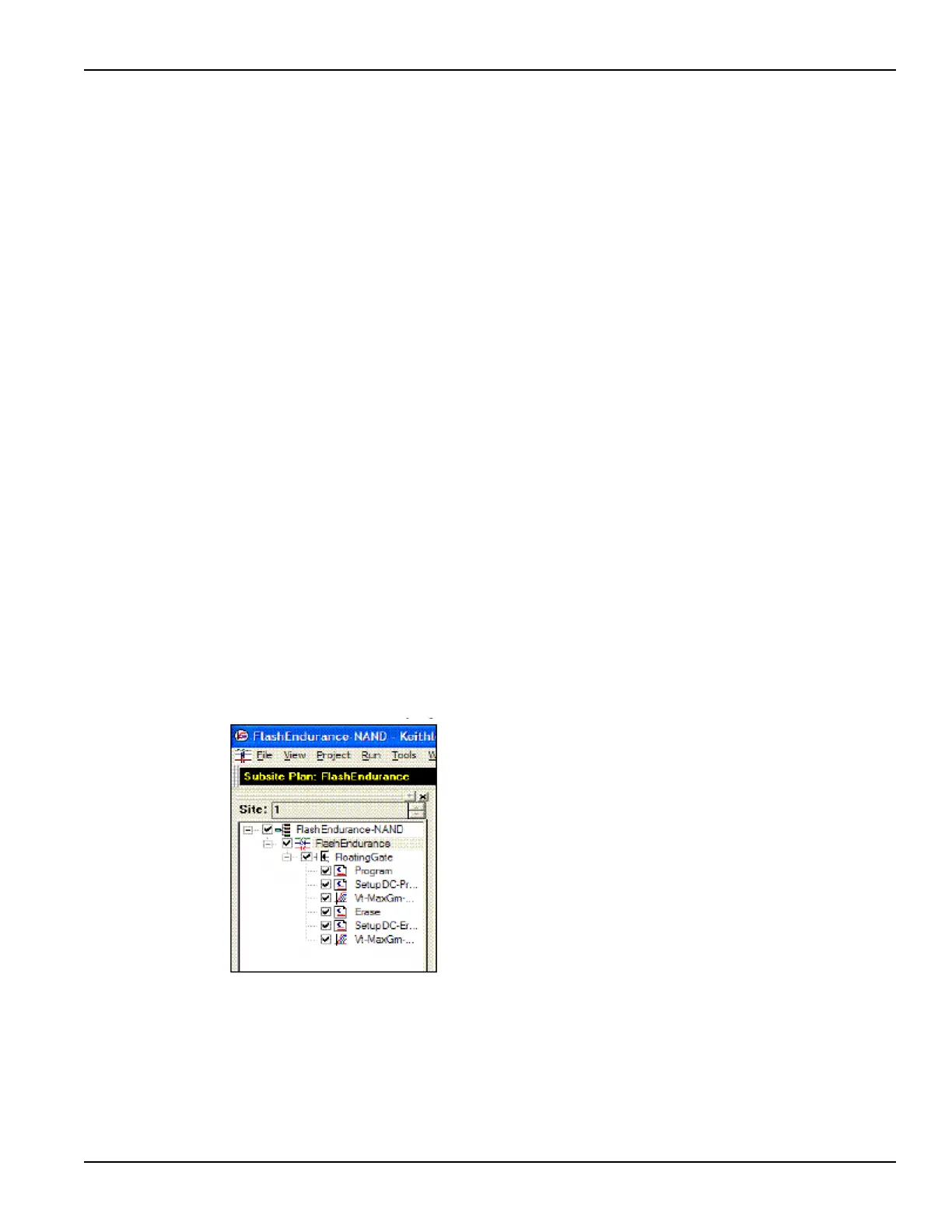
FlashEndurance-NAND tests
FlashEndurance-NAND tests consist of the following test:
• Program
• SetupDC-Program
•Vt-MaxGm-Program
•Erase
• SetupDC-Erase
•Vt-MaxGm-Erase
The project navigator for FlashEndurance-NAND is shown in Figure 3-112.
Stressing for the FlashEndurance-NAND tests are configured from the Subsite
Setup tab for the FlashEndurance subsite plan.
The default setup (shown in Figure 3-113 and Figure 3-114) uses Segment ARB
®
waveforms to perform log stressing that ranges from 1 to 100,000 counts.
The Segment ARB waveform files (Flash-NAND-Vg-ksf and Flash-NAND-Vd-ksf)
used for stressing are loaded into the Device Stress Properties window shown in
Figure 3-114. The stress properties window is opened by clicking the Device
Stress Properties button in Figure 3-113. Example results for the Endurance
tests are shown in Subsite Graph tab (see Figure 3-115).
Figure 3-112
FlashEndurance-NAND project plan

 Loading...