4-12 Return to Section Topics 4200-900-01 Rev. K / February 2017
Section 4: How to Control Other Instruments with the Model 4200-SCS Model 4200-SCS User Manual
Running test sequences
NOTE For detailed information about test and sequence execution, refer to the Reference
Manual, Run execution of individual tests and test sequences, page 6-162.
The ivswitch project uses the same ITMs that are used in the default project. The primary
difference between the two projects is that the ivswitch project uses connect UTMs to control the
switch matrix. As shown in Figure 4-13, there is a connect UTM at the beginning of each device
test sequence.
A test sequence for a device is executed by selecting the device plan, and then clicking the green
Run button .
When a device plan is started, the connect test closes the appropriate matrix crosspoints to
connect the instruments to the appropriate device.
All devices may be tested by selecting the Subsite Plan and clicking the green Run button .
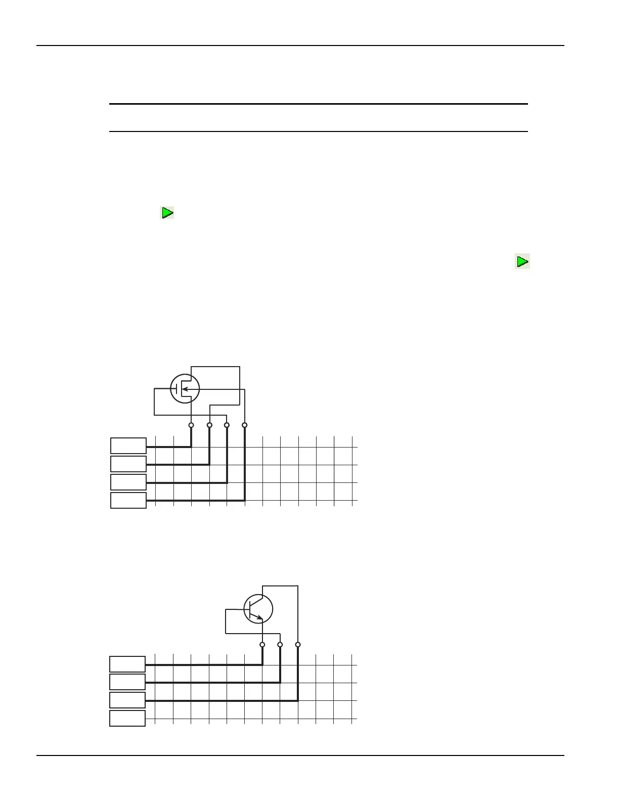
Figure 4-14 through Figure 4-18 show the signal paths that are automatically selected for the five
devices.
Figure 4-14
Signal paths for 4terminal-n-fet tests
Figure 4-15
Signal paths for 3terminal-npn-bjt tests
Gate
Source
Drain
Substrate
N-Channel
MOSFET
1
2
3
4
5
6
7
8
910
11
12
A
B
C
D
SMU1
SMU2
SMU3
GNDU
NPN
Transistor
Base
Emitter
1
2
3
4
5
6
7
8
910
11
12
A
B
C
D
Collector
SMU1
SMU2
SMU3
GNDU

 Loading...