3-106 Return to Section Topics 4200-900-01 Rev. K / February 2017
Section 3: Common Device Characterization Tests Model 4200-SCS User’s Manual
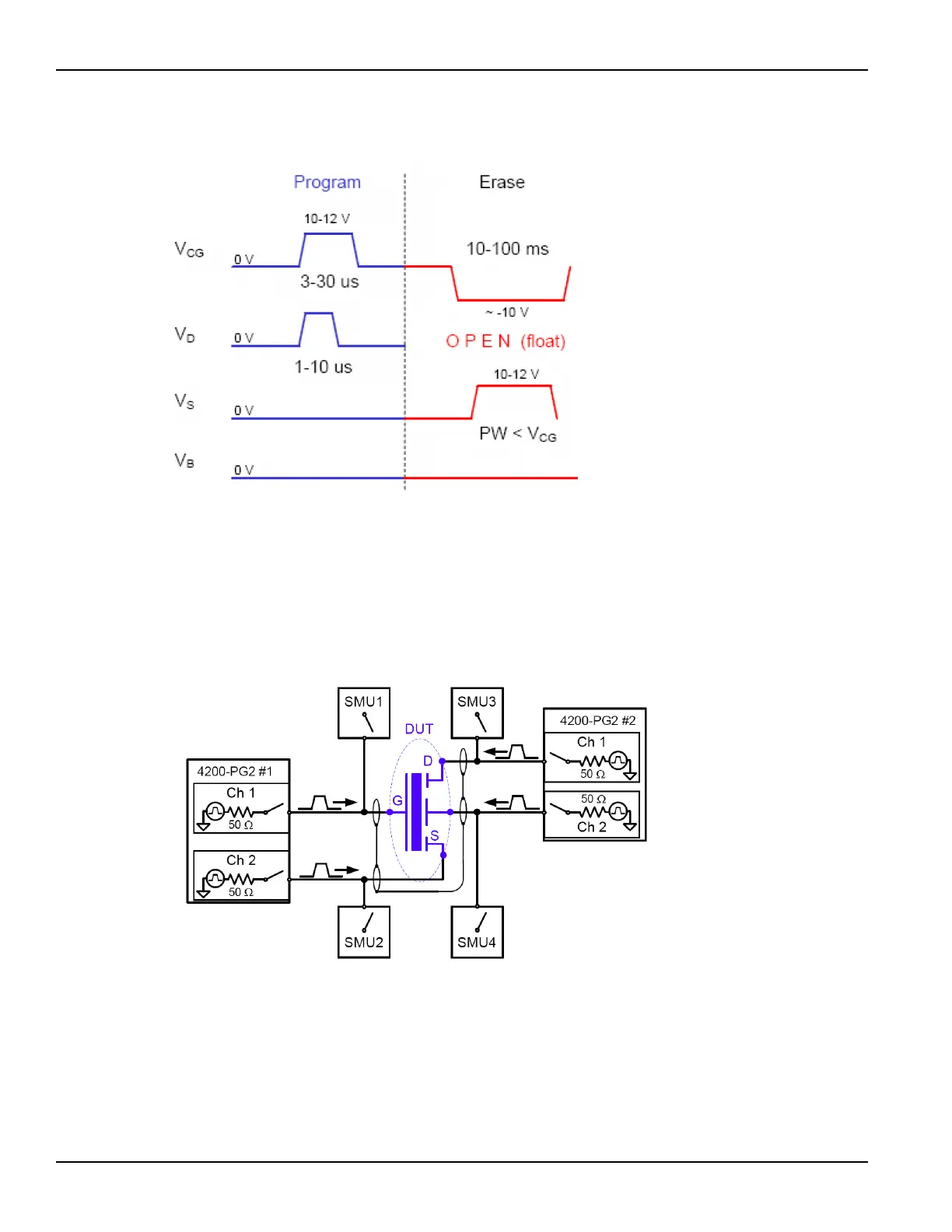
Figure 3-88
Program + Erase pulse waveforms for a floating gate DUT, with separate pulse waveforms
for the DUT gate, drain, source, and bulk.
The block diagram for the Flash setup is shown in Figure 3-89. Reconfiguring
from the pulse stress to DC measure phases is done by activating the switches on
the SMU and PG2 cards. During the pulse program / erase phase, the relays in
the PG2 channels are closed and the relays in the SMUs are open. For the DC
measure phase, the opposite is true.
Figure 3-89
Basic schematic of flash testing without a switch matrix
Endurance testing
Endurance testing stresses the DUT with a number of Program+Erase waveform
cycles, and then periodically measures both the voltage threshold in the
programmed state V
TP
, as well as the voltage threshold of the erased state, V
TE
.
The purpose of these tests is to determine the lifetime of the DUT, based on the
number of Program+Erase cycles withstood by the device before a certain
amount of shift, or degradation, in either the V
TP
or V
TE
, as shown in Figure 3-90.

 Loading...