4200-900-01 Rev. K / February 2017 Return to Section Topics 4-27
Model 4200-SCS User Manual Section 4: How to Control Other Instruments with the Model 4200-SCS
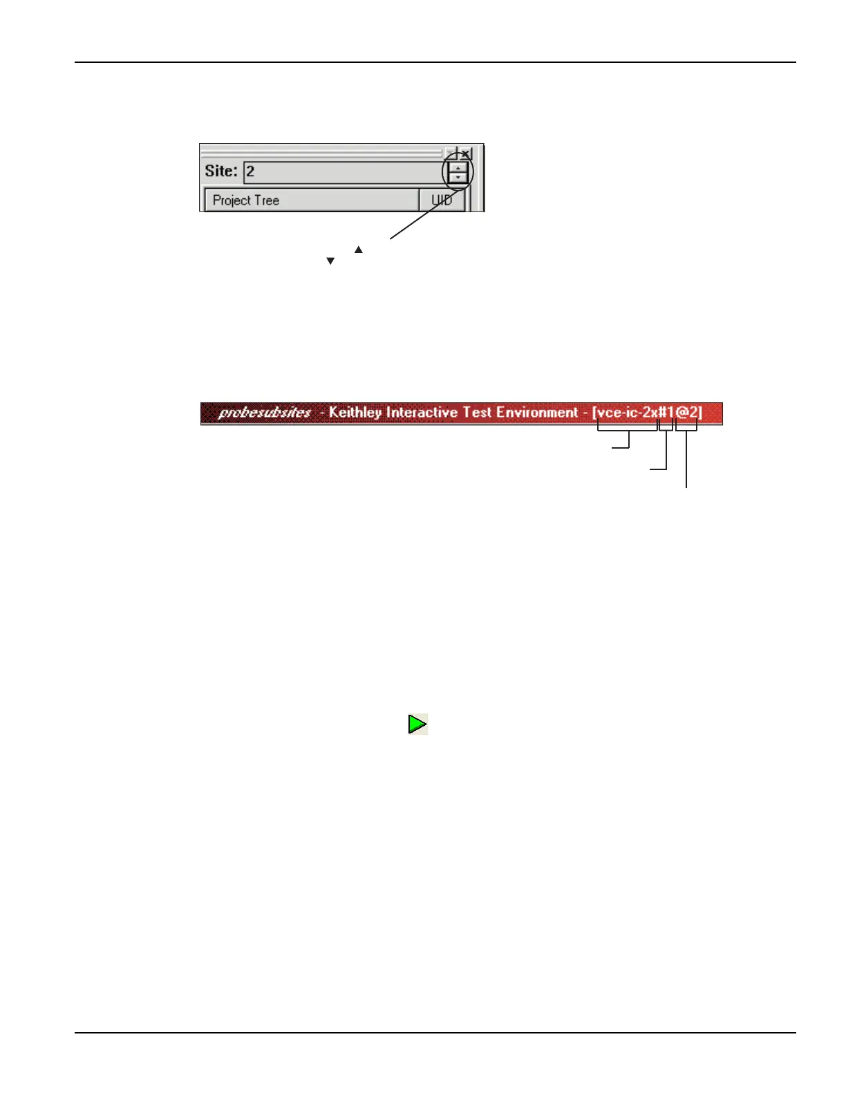
Figure 4-36
Site Navigator
The title bar at the top of the KITE panel indicates which test is presently being displayed. In
Figure 4-37, test vce-ic-2x for Site 2 is displayed. The unique identifier (UID) distinguishes this
test from any other test having the same name.
Figure 4-37
KITE title bar
Running individual plans or tests
You can run any subsite plan, device plan, or test in the project. The test sequence will stop after
the plan or test is finished.
To show how to run the 3terminal-npn-bjt device plan for subsite 2 of site 2:
1. Manually position the prober to test Subsite 2 of Site 2. Make sure the prober pins are
making contact with the subsite pads.
2. Set the site navigator to Site 2.
3. In the project navigator, click 3terminal-npn-bjt for Subsite2 to select the device plan.
4. Click the green Run button to start the test sequence.
How to control an external pulse generator
This tutorial demonstrates how to control a pulse generator to stress a semiconductor device and
analyze the effects of the stress. The applied stress is a burst of 3.5V pulses across the
gate-substrate (bulk) terminals of an N-channel MOSFET.
To run the basic test sequence:
1. Measure the transfer characteristics of the device before the stress.
2. Apply a stress burst of 3.5V pulses.
3. Measure the transfer characteristics of the device after the stress.
The after-stress characteristics can then be compared to the before-stress characteristics.
Click to increment or
to decrement site number
vce-ic-2x
(test name)
@2
(site number)
#1
(UID number)

 Loading...