4-18 Return to Section Topics 4200-900-01 Rev. K / February 2017
Section 4: How to Control Other Instruments with the Model 4200-SCS Model 4200-SCS User Manual
Test system connections
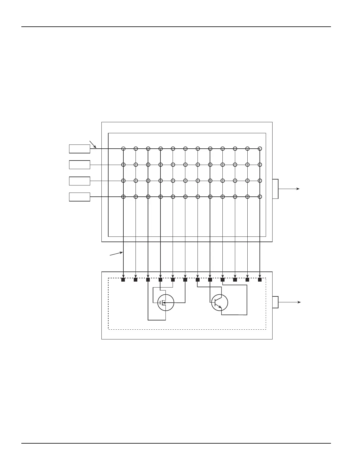
A typical test system for this tutorial is shown in Figure 4-22. As shown, the 4200-SCS and probe
station are connected to a 7174A matrix card. The matrix card is installed in the switch matrix, and
the switch matrix and probe station are controlled through the GPIB bus. For connection details as
well as information about the KCON utility, refer to the Reference Manual, Keithley CONfiguration
Utility (KCON), page 7-1.
Figure 4-22
System configuration for the probesubsites project
GPIB
To the
4200-SCS
(7007 Cable)
Model 7174A Matrix Card
Model 707 or 708 Switch Matrix
1
A
234 5 6 7 8910 11
12
B
C
D
SMU1
SMU2
SMU3
GNDU
Probe Station
Safety
Interlock
To the
4200-SCS
(236-ILC-3
Cable)
Pin
1
Pin
2
Pin
3
Pin
4
Pin
5
Pin
6
Pin
7
Pin
8
Pin
9
Pin
10
Pin
11
Pin
12
Drain
Substrate
Source
N-Channel
MOSFET
Wafer Subsite
Gate
4200-MTRX-X
or
4200-TRX-X
Cables
4200-TRX-X
Cables
Collector
Base
Emitter
NPN
Transistor

 Loading...