3-98 Return to Section Topics 4200-900-01 Rev. K / February 2017
Section 3: Common Device Characterization Tests Model 4200-SCS User’s Manual
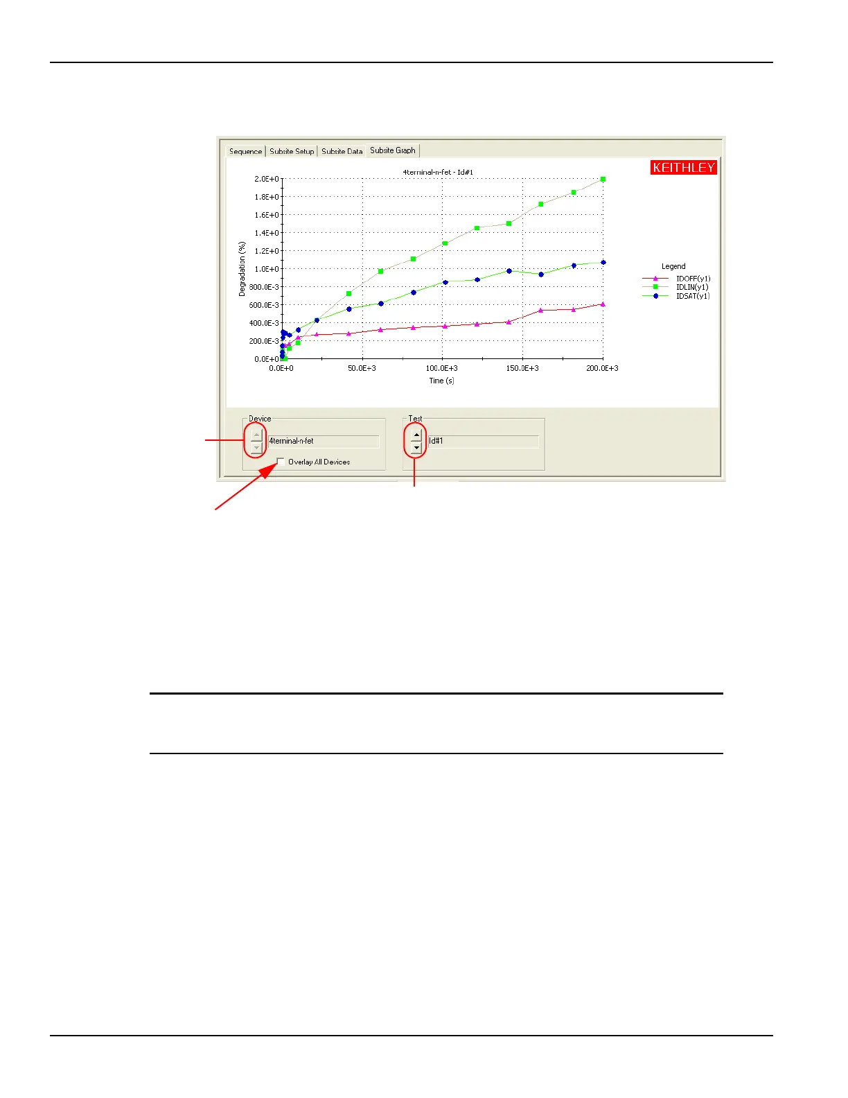
Figure 3-78
Subsite Graph tab: Stress / Measure Mode
Configuration sequence for subsite cycling
There are four project plans that use subsite cycling. These include HCI_1_DUT,
HCI_4_DUT, NBTI_1_DUT, and EM_const_I. The process flow for these projects
is shown in Figure 3-79.
NOTE A new project plan for subsite cycling can be created or one of the four existing
project plans can be modified as needed. For details, see the Reference manual,
Building, modifying, and deleting a Project Plan, page 6-48.
When adding a device plan or test to a subsite cycling project, the following
sequence must be followed:
1. Insert a device plan for the type of device to be tested. For example, if testing a 4-terminal,
n-channel MOSFET, insert the 4terminal-n-fet device into the subsite plan.
2. Under the device plan, insert a new test (ITM or UTM) or copy a test from the test library
and make the proper modifications.
3. Use the Formulator for the ITM or UTM to configure data calculations on test data.
• The window to set the formulator is opened by clicking the Formulator button on the
definition tab of the ITM or UTM.
– For more information about how to use the Formulator, refer to the Reference
manual, Analyzing test data using the Formulator, page 6-287.
1. Use to select
device.
2. Use to select test.
Select (check) to display all the graph
traces for all devices that were
measured by the selected Test.
NOTE
For a single-device
subsite plan, the
Device select buttons
and the checkbox to
Overlay All Devices
are disabled.
For a single-test
subsite plan, the Test
select buttons are
disabled.

 Loading...