4200-900-01 Rev. K / February 2017 Return to Section Topics 3-65
Model 4200-SCS User’s Manual Section 3: Common Device Characterization Tests
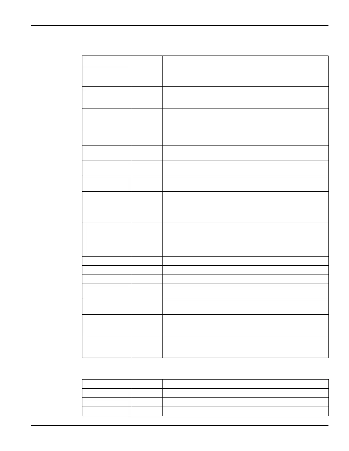
Table 3-22
Inputs for scopeshot_pulseiv
Input Type Description
RiseTime double The gate pulse transition rise time (s). This can be set from 10 e-9 to
300 e-9 in 10 e-9 (10 ns) steps. This value programs the full transition
time (0–100%), not the 10–90% time.
FallTime double The gate pulse transition fall time (s). This can be set from 10 e-9 to 300
e-9 in 10 e-9 (10 ns) steps. This value programs the full transition time
(0–100%), not the 10–90% time.
PulseWidth double The gate pulse width (PW). The PW can be 20 ns to 1us (10 ns
resolution). Pulses wider than 150 ns will begin to be attenuated by the
capacitor in the 4200-RBT.
PulseBase double The pulse gate base voltage. This can be set from -5 to +5 V, inclusive
of amplitude.
PulseAmplitude double The pulse gate voltage amplitude. This can be set from -5 to +5 V,
inclusive of base voltage.
GateLoad double The scope card channel 1 input impedance for the gate. Either 50 or
1E6. Use 50 for Pulse IV with RBTs.
GateRange double The scope card channel 1 Y scale voltage range for the gate
measurement. Typical values are 1, 2, 5 V.
DrainLoad double The scope card channel 2 input impedance for the drain. Either 50 or
1E6. Use 50 for Pulse IV with RBTs.
DrainRange double The scope card channel 2 Y scale voltage range for the drain
measurement. Typical values are 1, 2, 5 V.
PulsePeriod double The pulse period for the Vgs pulse. The period can be set from 40 ns to
1 s (10 ns resolution). The period must be set so that the Duty Cycle
(DC) is no more than 0.1%. This period is most easily calculated by
multiplying the largest desired pulse width (PW) by 1000. Example: PW
= 150 ns, so Period = 150 us.
AverageNum int The number of waveforms to average.
GateBias double The DC gate bias, provided by the gateSMU.
DrainBias double The DC drain bias, provided by the drainSMU.
VPUID char * The instrument ID. This should be set to VPU1 for 4200 systems with
the 4200-PIV package.
GateSMU char * The SMU used for the Gate. This can be SMU1 up to the maximum
number of SmUs in the system.
DrainSMU char * The SMU used for the Drain. This can be SMU1 up to the maximum
number of SMUs in the system. This is the SMU that applies the DC
bias to the DUT drain during the sweep.
TimeSize
Ch1OutSize
Ch2OutSize
int Set to a value that is at least equal to the number of steps in the sweep
and all three must be the same value.
Table 3-23
Outputs for scopeshot_pulseiv
Output Type Description
Time double * Array of time values from the scope card (s).
Ch1Out double * Array of gate voltages from channel 1 of the scope card.
Ch2Out double * Array of drain voltages from channel 2 of the scope card.

 Loading...