4200-900-01 Rev. K / February 2017 Return to Section Topics 3-129
Model 4200-SCS User’s Manual Section 3: Common Device Characterization Tests
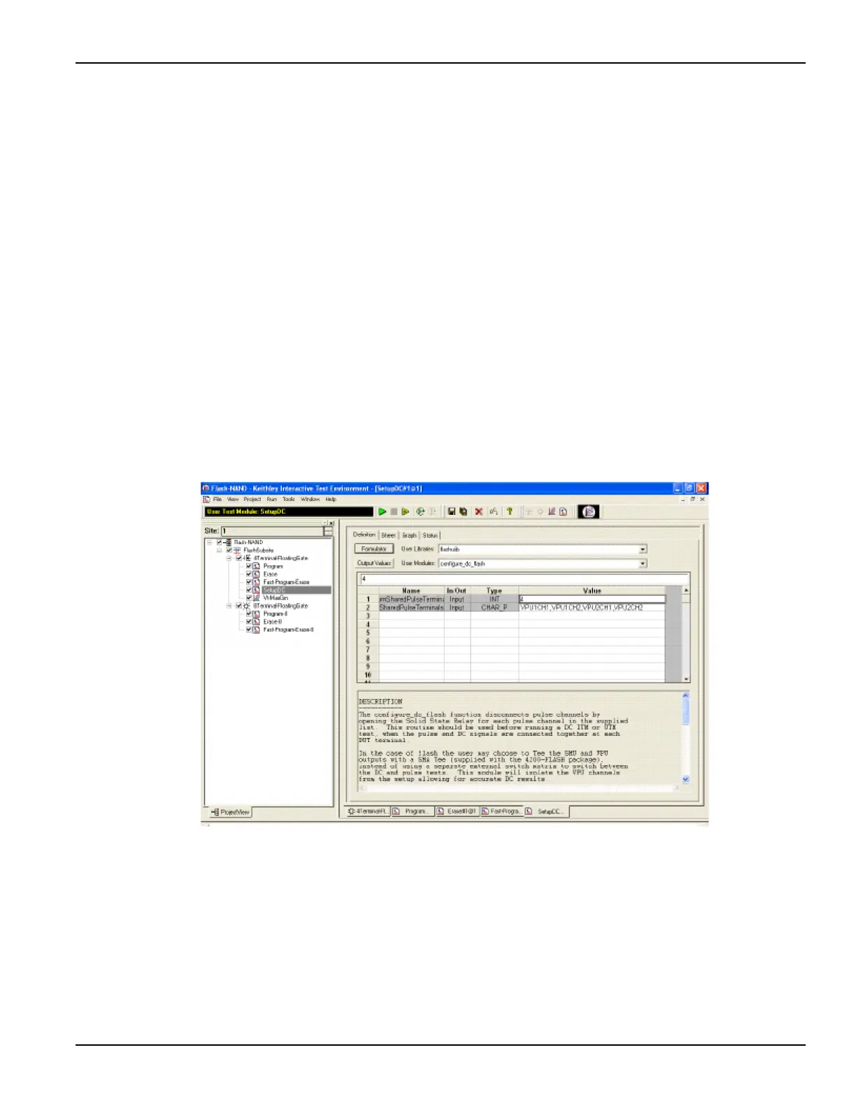
SetupDC test – The Definition tab for this test is shown in Figure 3-107. This test
isolates the VPU outputs from the DUT, allowing the SMUs to perform a DC
without signal interference from the pulse outputs. It does this by opening the
HEOR for each VPU channel in the PulseTerminals list.
Disconnecting the VPU channels allows for accurate DC results. This isolation
step is only necessary when using the direct connect method (see Figure 3-95
and Figure 3-96), where the SMU and VPU signals are sharing a single
connection to each device terminal (see Figure 3-89).
The same test step is called Open-VPU-Relay, and is optional for switch matrix
configurations (see Figure 3-97), but is recommended to prevent accidental
simultaneous connection of both SMU and PG2 channels to a single terminal.
The SetupDC test step is used in the configuration without a switch matrix and is
required before any DC tests. When using a switch matrix, a ConPin test can
replace the SetupDC test (see Reference manual, LPT functions, page 8-91) to
set the appropriate matrix connections prior to any DC tests.
Figure 3-107
Flash-NAND project – SetupDC definition tab
Vt-MaxGm test – This test is used to perform a DC voltage sweep on the gate of
the DUT and measure the drain current at each sweep step. The default Definition
tab for this test is shown in Figure 3-108. SMU3 is configured to perform a 101
point sweep from 0 to 5 V in 50m V steps. SMU1 is configured to DC bias the
drain at 0.5 V and measure current at each step of the sweep.

 Loading...