Page 46 Transport/Start up Group 5
Release R1.06 JET3up
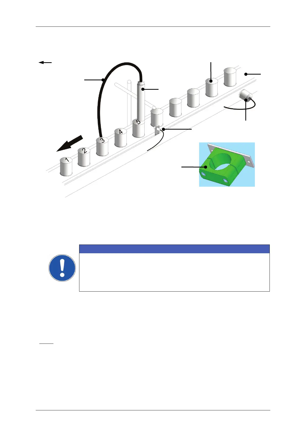
Figure 7 Print head installation (Example)
6 – Umbilical (Hose connection)
ATTENTION
The print head should be attachted vibration-free. The hose
connection of the print head should not be smaller as a radius of
R=100 mm statistically (loop: 200 mm) and dynamically not below
R=150 mm (loop: 300 mm)!
Torsional shear stress must be avoided!
The distance of the print head to the product depends on the required character
height. As smaller the required character height, as smaller the distance of the print
head to the product (smaller distances produce better type quality)
Note:
In general a distance of round about 8-10mm is recommended.
For applications with extreme small or large character heights a micro-
head are available optionally.