EasyManua.ls Logo

Leibinger JET3 up - Figure 28 Assembly of the External Print Head Ventilation

Leibinger JET3 up
412 pages
Print Icon
To Next Page IconTo Next Page
To Previous Page IconTo Previous Page
Loading...
Page 90 Job Editor Group 8
Release R1.06 JET3up
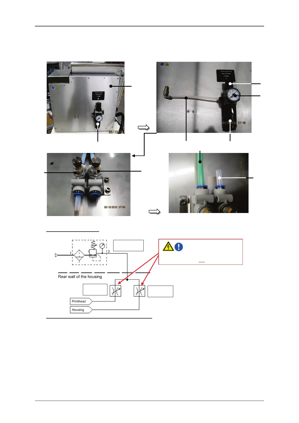
Figure 28 Assembly of the external print head ventilation
Outside
Inside
Connection diagram:
1 rear panel of the housing
3 Supply air hose
2 pressure regulator valve
4 Throttle valve for the head ventilation
2.1 adjusting knob
5 Throttle valve for the housing ventil.
2.2 manometer
6 Hose for the print head ventilation
2.3 Condensate container (cartridge)
7 Hose for the housing ventilation
1
2
3
2.1
6
7
2.3
2.2
5
4
70 l/h
30 l/h
1,4 Bar
Both of the throttle valves are adjusted
exactly and should not be changed!

Table of Contents

Other manuals for Leibinger JET3 up

Related product manuals