Group 5 Transport/Start up Page 63
JET3up Release R1.06
Basic data /Recommended working conditions:
(or high resistance)
Reset Counter
of bounce
Depending on assigned function
(see following table)
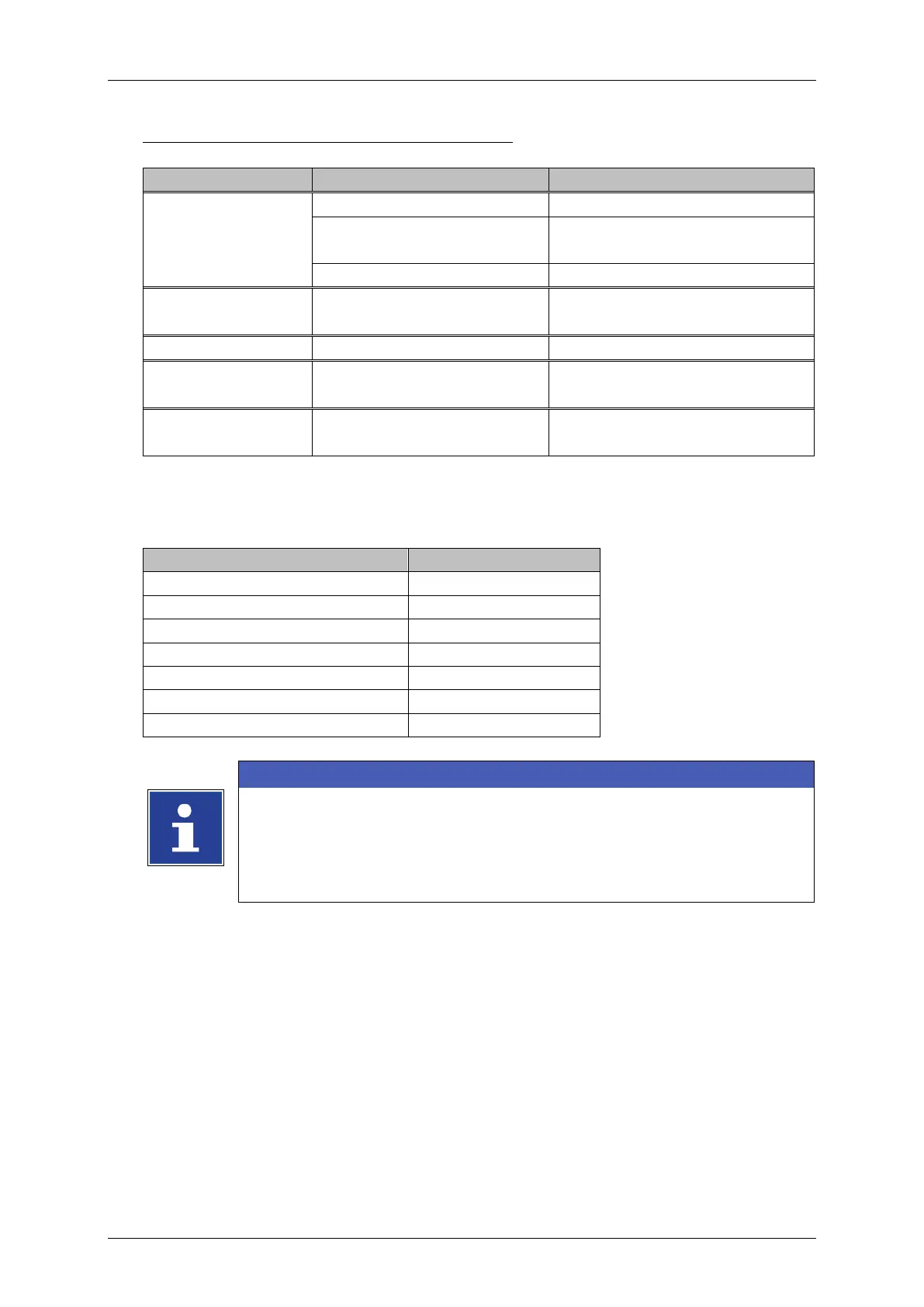
In the following table you will find the minimum pulse widths which are required to
release the assigned function at the X4 plug.
Gauger synchronization signal
The function allocations of the inputs 0 up to 5 happens by the
software of the JET3up in the menu
Settings
I/O-Settings
Inputs.
You will find a circuit diagram of the interface in the manual
appendix!
(1)
all 24V power supply outputs on X1, X3, X4 and X5 are distributed over a common resettable
fuse with 700mA max. current.
Please ensure that the sum of current are not exceed 700 mA.
(2)
If one or more of the jobselect inputs were changed the changes must be completed
( = all signals are stable) within this time.