Diagnostic information 2-133
7462
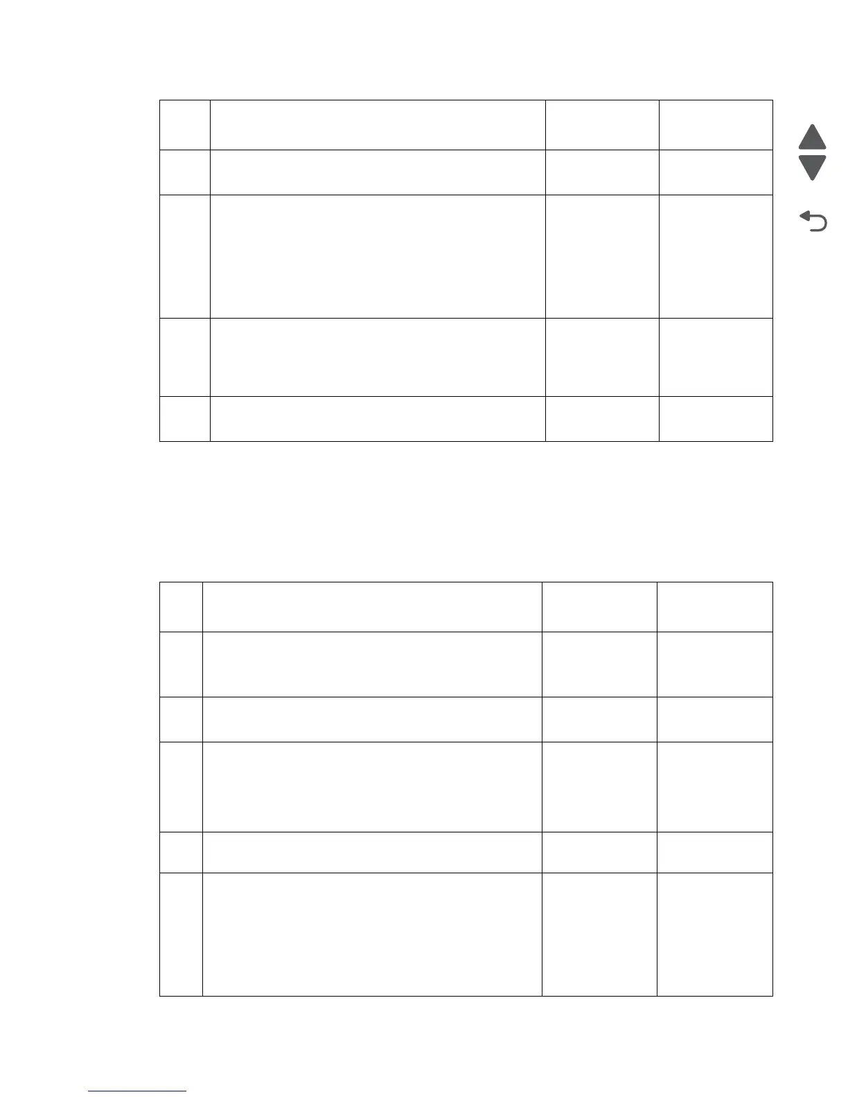
Sensor (fuser output) late jam service check.
Step Check Yes No
1 Check the media path for partially fed or jammed media.
Is the media path free from partially fed or jammed media?
Go to step 2. Remove any pre-
staged or jammed
media.
2
Check the sensor (input) for proper operation.
1. Enter the diagnostic mode
2. Select Base sensor test
3. Observe the line item “input”
Does the display on the operator panel, change every time
the sensing area of the above sensor is interrupted or
blocked.
Go to step 4. Go to step 3.
3
Check the above sensor for proper connection.
Is the above sensor connected properly?
Replace the
Sensor (input).
Go to “Sensor
(input) removal”
on page 4-41.
Replace the
connection.
4
Perform a print test.
Does the problem remain?
Contact next
highest level of
tech support.
Problem resolved.
Use this procedure for the following jams:
• 201.02 • 201.07 • 201.27 • 201.32 • 201.50
• 201.52 • 201.57 • 201.75 • 201.77 • 201.82
Step Check Yes No
1 Check the media size setup and tray guides for all media
trays.
Does the media size, in use, match the size set for all media
trays?
Go to step 2. Replace the
media, or change
the media size
setup.
2
Check all the media trays for proper media installation.
Is the media properly installed in all the media trays?
Go to step 3. Remove and
properly re-install
the media.
3
Check the fuser unit assembly for damage and life
expiration.
Is the above component damaged or has it exceeded life?
Replace the fuser
unit assembly.
Go to “Fuser unit
assembly
removal” on
page 4-16.
Go to step 4.
4
Check the fuser unit assembly for obstructions.
Is the above component free from obstructions?
Go to step 5. Remove
obstructions.
5
Check the sensor (fuser output) for proper operation.
1. Enter the diagnostic mode
2. Select Base sensor tests
3. Observe the line item “output”
Does the display on the operator panel, change every time
the sensing area of the above sensor is interrupted or
blocked.
Go to step 7. Go to step 6.
 Loading...