Repair information 4-89
7462
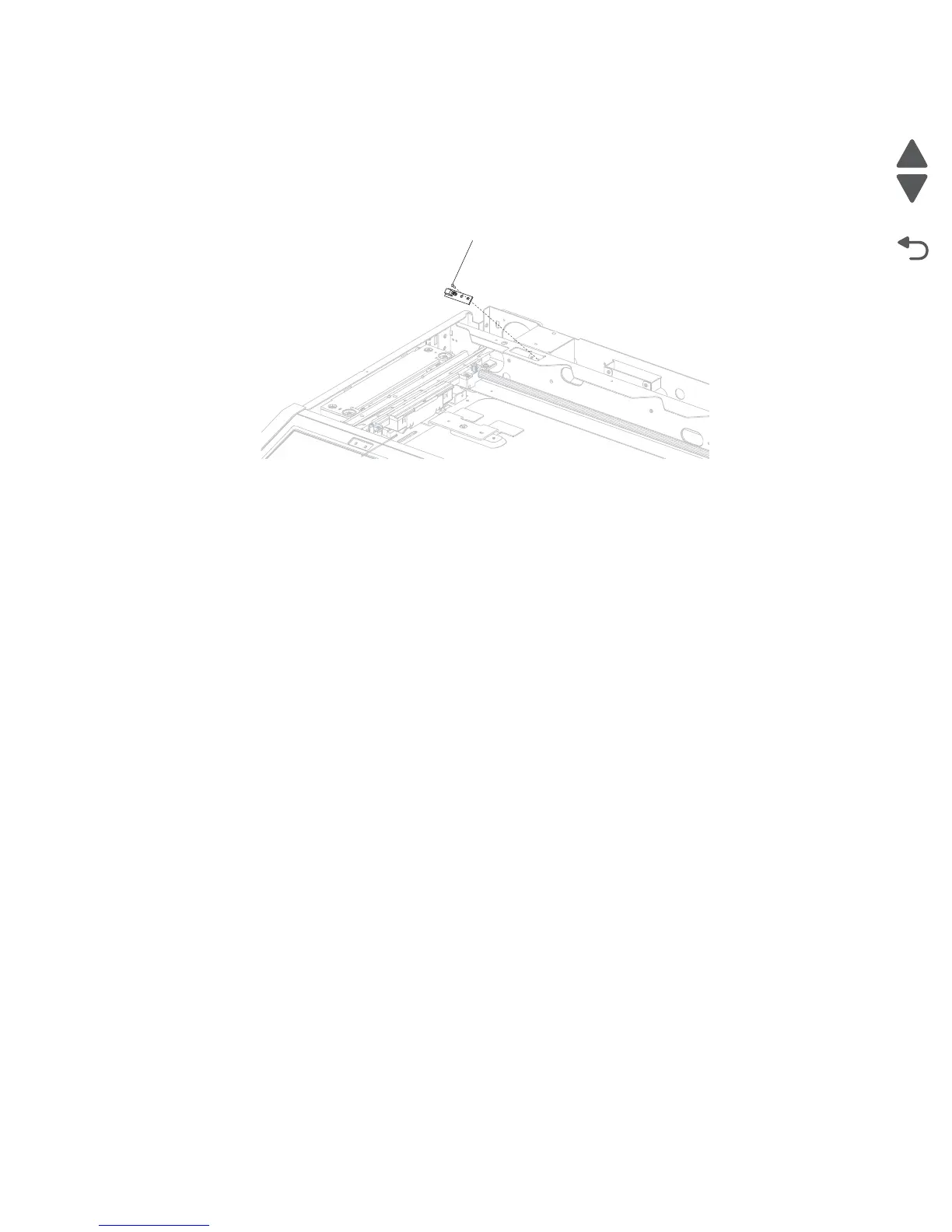
Scanner reference LED cable assembly removal
1. Remove the scanner platen glass cover assembly. See “Scanner platen glass cover assembly removal
(models X651, X652, X654 and X656)” on page 4-137 or “Scanner platen glass cover assembly
removal (model X658)” on page 4-136.
2. Remove the screw (A) securing the scanner reference LED cable assembly to the flatbed frame.
3. Remove the scanner reference LED cable assembly.
4. Remove the wire harness from the scanner reference LED cable assembly.
Scanner unit assembly removal (models X651, X652, X654 and X656)
Warning: When replacing any of the following components:
• Scanner interface card assembly
• System card assembly
• Scanner unit assembly
Only replace one component at a time. replace the required component and perform a POR before replacing a
second component listed above. If this procedure is not followed, the printer will be rendered inoperable. Never
replace two or more of the components listed above without a POR after installing each one or the printer will
be rendered inoperable.
These components can be used as a method of troubleshooting as long as the machine is booted into diagnostic
mode or is operating in diagnostic mode. Once a component has been installed in a machine and powered up
into user mode, it cannot be used in another machine. It must be returned to the manufacturer.
1. Remove the ADF unit assembly. See “ADF unit assembly removal (models X651, X652, X654 and
X656)” on page 4-80.
2. Remove the scanner controller card cage cover.
3. Remove all cables.
 Loading...