Chapter 9 NC Control Function
SIN, COS, TAN, ATAN,
SQRT, ABS, ROUND,
AND, OR, RIX, FUP
9.1.3 Coordinate System
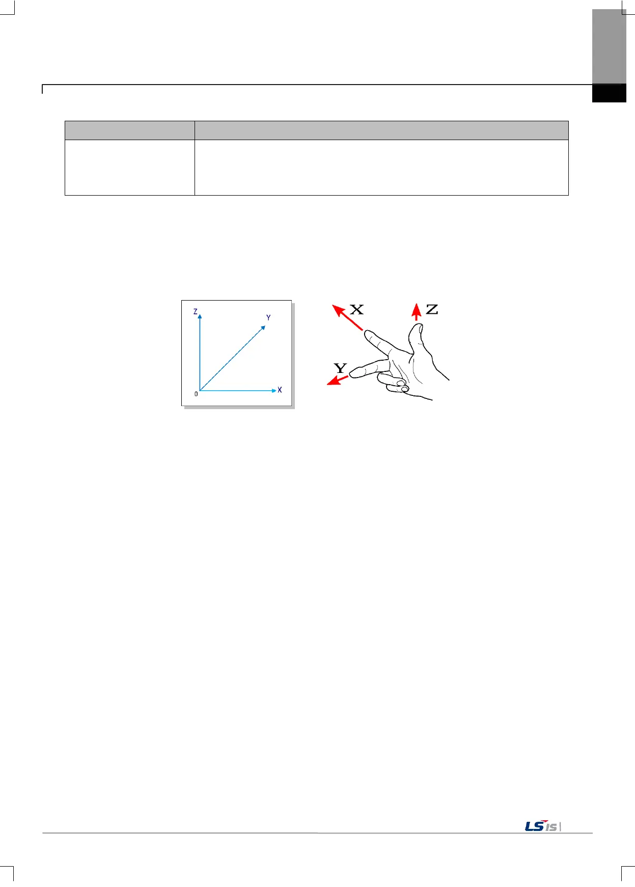
The coordinate system means the space to be used as a basis for operating the machine. The motion controller
uses the right-handed rectangular coordinate system and supports four modes: machine coordinate system, work
coordinate system, local coordinate system, and relative coordinate system.
[Basic coordinate system]
(1) Machine coordinate system
Each machine used for motion control has its own specific position setting, and the coordinate system is set
based on this specific position. This particular position is the "machine origin" of the machine, and the coordinate
system based on this machine origin is the "machine coordinate system". The "machine origin" and its
accompanying "machine coordinate system" differ depending on the machine to which the motion controller is
applied. Accordingly, please refer to the instruction manual of the applicable machine.
Generally, when power is applied and the machine is started, homing is performed first. After homing, the reset
machine position is reset to "0" position and at this time, the machine coordinate system is changed to the origin
position. However, in the case of machinery equipped with the absolute encoder-positioning feedback, the absolute
position is maintained independent of homing.
For more details on setting the machine coordinate system, refer to the G53 command description.
(2) Workpiece coordinate system
The workpiece coordinate system means the coordinate system whose origin is the machining reference point of
the product. Generally, the origin of the workpiece coordinate system is set by the workpiece coordinate system
setting command. When the workpiece coordinate system is set, since then, the command operates at the new
coordinate whose origin is the machining start point of the product. For the setting (G92) and selection (G54 ~
G59) of the workpiece coordinate system, please refer to the description section of the commands.

 Loading...
