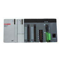
Chapter 3 Operation Order and Installation
Chapter 3 Operation Order and Installation
Here describes the Operation order of motion controller.
External emergency stop signal
External upper limit signal
External lower limit signal
Home signal
DOG signal
Reading/Writing servo parameter and servo tuning are
available by XG5000
Allocate the axis number to each servo by using
XG5000
Connect the motor and external signal to the servo
Write the servo parameter in the XG5000 and download it to servo
Connect Ethernet communication cable between positioning
module and servo, and between servos
Write the motion program and parameter of motoin controller in
the XG5000 and download it to the Controller
Set up the servo axis and establish communication between Servo
and motion controller
Specify the number of axis to be connected
Specify the servo type and capacity
Install the XG5000 on the PC
Mount the motion controller on the base
Specify motion control operation method and control unit
Turn the motion controller on
Connect the communication cable between USB(Ethernet) ports
of PC and motion controller
Execute a test run by using XG5000
Write the program for motion control operation through XG5000
Start the motion control operation
Max. Communication distance: 100m
Communication cable: STP cable
Check whether RDY LED is ON or not
Basic parameter, axis group parameter, master
parameter, common parameter, motion program
Check the operation status and modify the module
parameter and servo parameter

 Loading...