Chapter 2 Specification
2.4 The Name of Each Part
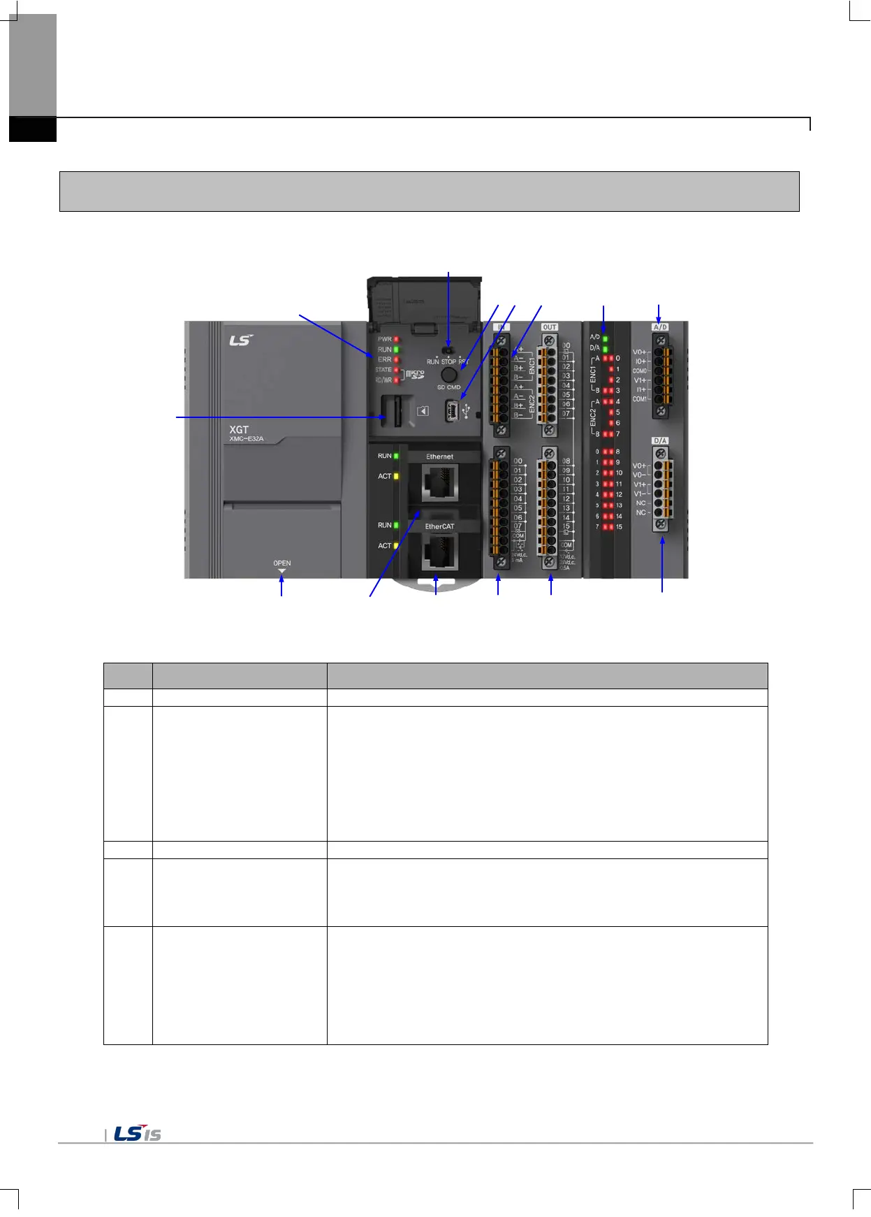
2.4.1 The Name of Each Part
No. Name Description
AC 110/220V power input, LG terminal, DC24V output
② Staus display LED
Displays the motion controller’s operation mode.
• PWR(Red light on): The power is supplied
• RUN(Green light on): During RUN mode
• ERR(Flickering Red light): Occurrence of errors during operation
• STATE(Red light on/Flickering Red light): When the SD card is
installed, the red light is turned On; when the SD card error occurs,
the red light is flickering.
• RD/WR(Flickering Red light): During SD memory reads or writes
Connector with the SD memory card
④ Mode switch
Sets the motion controller’s operation mode.
• RUN: Program’s operation is executed.
• STOP: Program’s operation is stopped.
• RST: Program’s operation is reset.
⑤ SD card command button
Press to button less than 3 second.
• Additional function(back-up, recover, compare) operation in
according to script setting
Press to button over 3 second.
• SD Power On/Off
Pressing to button and power on

 Loading...
