Plockmatic BM3050 system 27 August 2019 3. Repairs and adjustments (REP and ADJ)
3-309
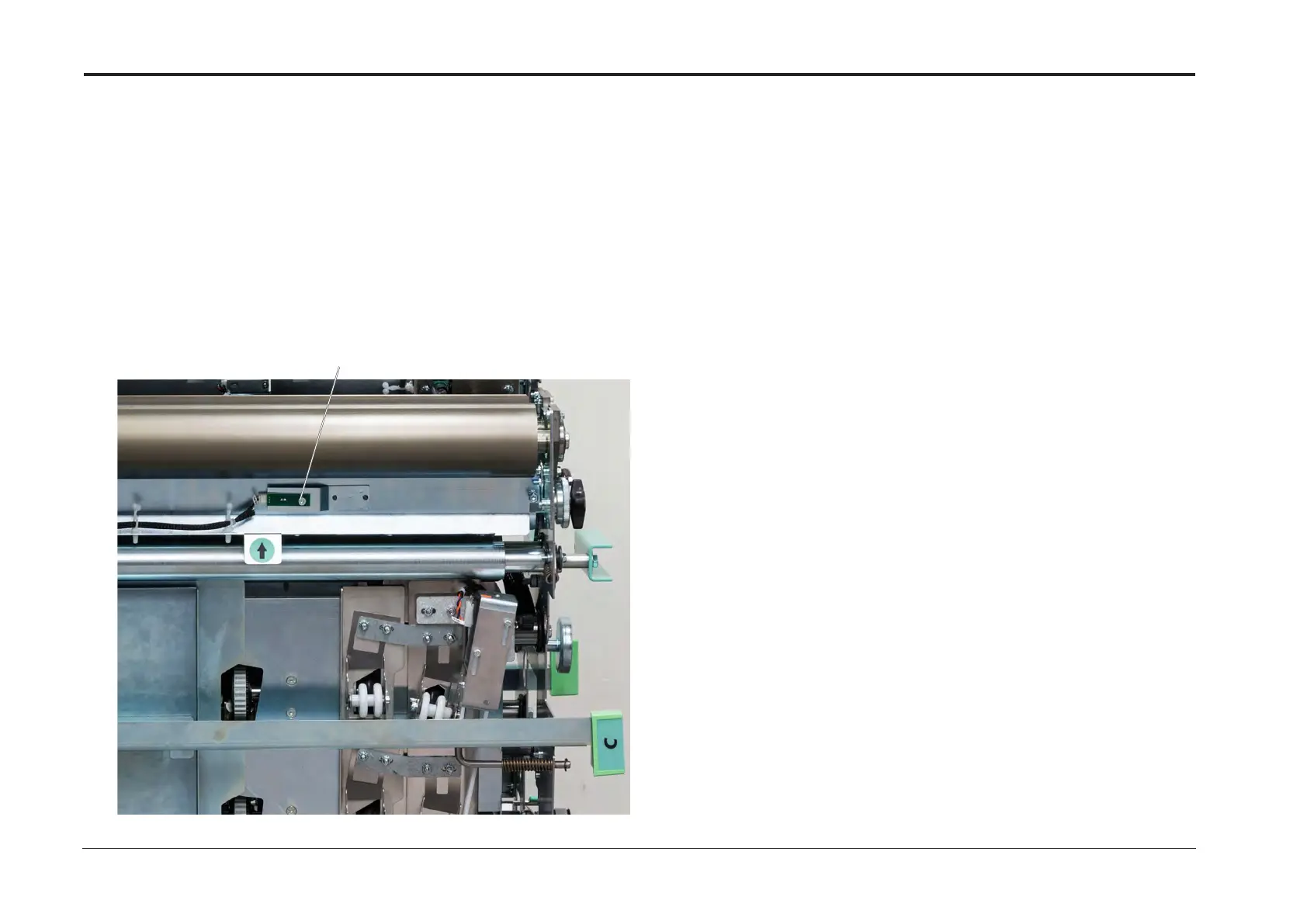
ADJ 12.54 Creaser Trigger Sensor (CT-Q4)
Phototransistor
Adjustment
1. Enter the service mode (GP1).
2. Check creaser trigger sensor CT-Q4 phototransistor according to section 5.
3. Align the Creaser Trigger Sensor (CT-Q4) Phototransistor and tighten screw [A]
to achieve a reading lower than 0.5V when not activated.
Purpose
To position the Creaser Trigger Sensor (CT-Q4) Phototransistor correctly.
ADJ 12.55 Creaser Tools M6 Home Sensor (CT-Q5)
Purpose
To position the Crease correctly in the middle of the paper,
so that the Coarse Tool with 0.0mm correction on the UI, will produce a crease in the middle of the sheet.
Adjustment
1. Set Units to metric.
2. Set the Coarse Tool correction to 0 and.
3. Select Creasing Coarse.
4. Select SRA3T or 12”x18”T format.
5. Ensure that the Face Trimmer is set to off.
6. Perform / check Registration Secondary Alignment Rail (ADJ 12.49)
7. Process one sheet of SRA3 or 12”x18”.
Measure the distance from the Lead Edge to the center of the Crease.
Calculate the difference in 0.1mm units.
Difference = Measured distance from Lead Edge - Theoretical distance from Lead Edge.
8. Adjust NVM value if the difference is bigger than ±0.5mm.
9. Enter the service mode (section 5).
10. Select the CST.
11. Enter NVM Values.
12. Add the Difference calculated in step #7 to the current value in NVM Value Index CT Creasing Offset.
13. Leave Service Mode (section 5).
14. Process one sheet of SRA3 or 12”x18”.
15. Measure the distance from the Lead Edge to the center of the Crease.
Calculate the difference in 0.1mm units.
Difference = Measured distance from Lead Edge - Theoretical distance from Lead Edge.
Adjust NVM value if the difference is bigger than ±0.5mm.
[A]
 Loading...


