Plockmatic BM3050 system 27 August 2019 4. Troubleshooting (RAP)
4-48
This RAP is for troubleshooting the Creaser Motor CT-M6.
Initial Actions
• Enter Service (GP 1)
• Check motor CT-M6 (PL 12.14) and CT-M7 (PL 12.15) according to GP4
• Ensure that plugs H.P1, H.P2, H.P3, H.P4, H.P5, H.P6 are
properly connected to Stepper Motor Driver PCB “H” (PL 12.21)
• Check that motor CT-M7 system works OK
Procedure
• Turn off the main switch while turning M6 transmission by hand to
rule out mechanical binding and/or other mechanical problems in the transmission.
• Go to Creaser Motor CT-M6 Transmission RAP and
verify that all transmission components move as indicated.
The M6 transmission works OK?
Y N
Fix problem.
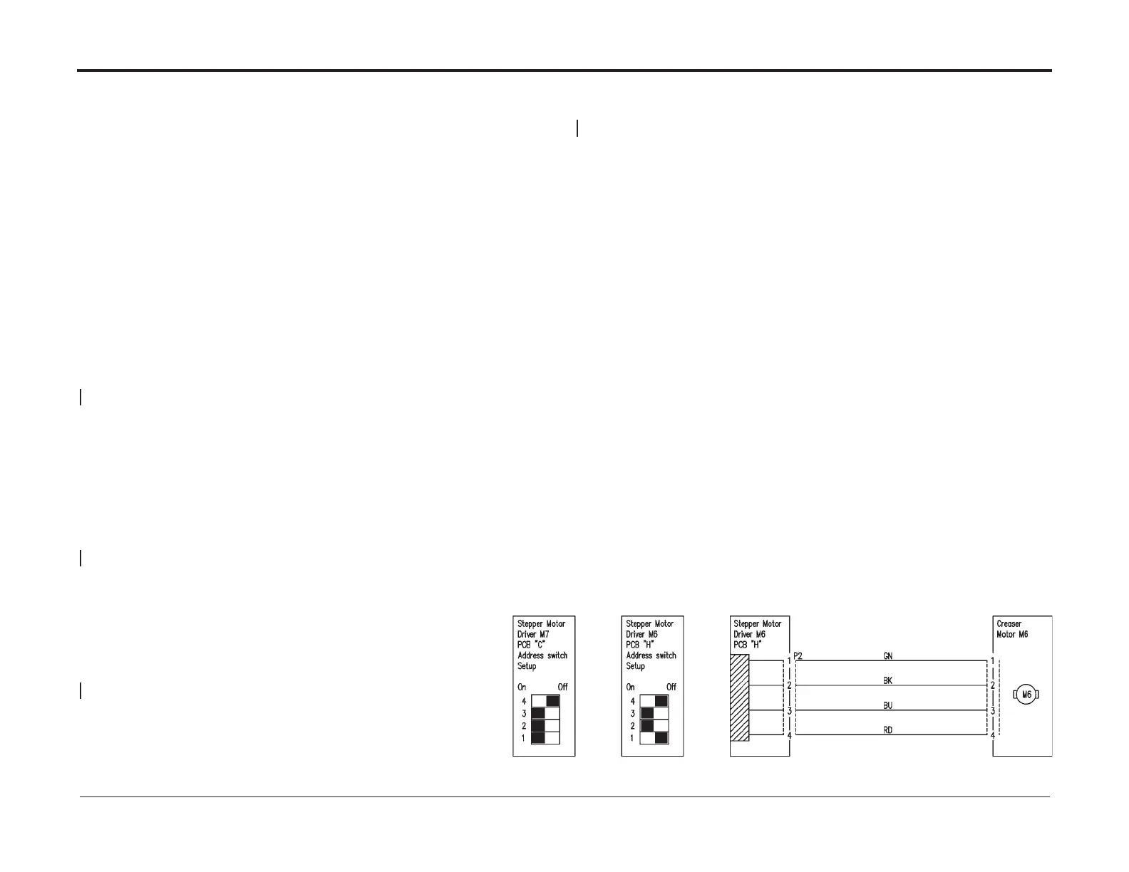
• Swap the Stepper Motor Driver (CT-M7) PCB “C” (PL 12.12) with
the Stepper Motor Driver (CT-M6) PCB ”H” (PL 12.21).
After swapping the Stepper Motor PCBs,
set the address dip switches to the settings in the Circuit Diagram.
• Check motor CT-M7 functionality.
The M7 system works OK?
Y N
Replace the Stepper Motor Driver (CT-M7) PCB “C” (PL 12.12)
Check for continuity between pins H.P2-1 and H.P2-2.
Check for continuity between pins H.P2-3 and H.P2-4.
There is continuity between pins H.P2-3 and H.P2-4.
There is continuity and no short circuit.
Y N
Repair harness.
Check for voltage at H.P3 between pins H.P3-1 and H.P3-2.
Creaser Motor CT-M6 RAP
The Voltage is 48VDC±10%
Y N
Go to Stepper Motor Driver (CT-M6) PCB “H” RAP
Replace Creaser Motor (CT-M6) (REP 12.55).


 To Next Page