Plockmatic BM3050 system 27 August 2019 3. Repairs and adjustments (REP and ADJ)
3-264
WARNING!
Turn off the VF602 Main Power Switch and disconnect the Main Power Cord before
disconnecting, removing or replacing any electrical components or measuring
resistance inside the machine.
1. Remove Cover, Rear (REP 15.0)
2. Disconnect connectors
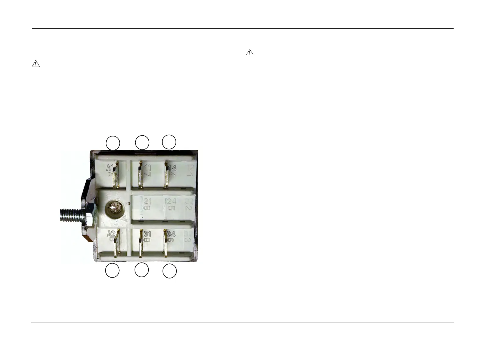
3. Remove screws (x2) and nuts (x2) and remove relay
General:
1. Remove connectors
2. Remove PCB
3. Mount new PCB
4. Replace connectors, see gure on next page
5. Make sure the DIP switches are in the correct position (see either sec-
tion 4 or section 8 of the Service Manual)
6. Load software according to Service Manual System BM3050 Section 5
Replacement
Reverse removal procedure.
Connect according to marking on connectors and relay
PCB CPU APP 32 (PCB “A”) Main Board
Perform NVM reset according to Service manual System BM3050 section
5
NOTE: USDS sensors (Q301/Q302) do not need to be calibrated.
PCB CPU APP 32 (PCB “H”) Upper bin
1. Perform NVM reset according to Service Manual System BM3050 sec-
tion 5
2. Calibrate US DSD sensor (Q102) according to BM3050 Operators
Manual, VF602 Sensor Calibration Section
3. Calibrate Optical DSD sensor (Q101) according to BM3050 Operators
Manual, VF602 Sensor Calibration Section
34
31
A2
14
11
A1
CAUTION
ESD Hazard! ESD (Electrostatic Discharge) can cause software crashes, data and/or
communications problems. Failure to use proper ESD procedures will cause dam-
age to electronic components (example: PCBs). ESD problems can be minimized by
maintaining all machine ground connections, ensuring the proper handling of circuit
boards/ sensors, refer to the general caution description at the beginning of section 3.
- Use ESD protection when working near PCBs. Failure to use ESD protection is likely
to result in a PCB failure.
PCB CPU APP 32 (PCB “L”) Lower bin
1. Perform NVM reset according to Service Manual System BM3050 sec-
tion 5
2. Calibrate US DSD sensor (Q202) according to BM3050 Operators
Manual, VF602 Sensor Calibration Section
3. Calibrate Optical DSD sensor (Q201) according to BM3050 Operators
Manual, VF602 Sensor Calibration Section
Continued on next page....
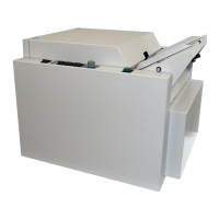
(VF602 Spare Parts Manual, PL6.0 Items 18,19,21,30) (VF602 Spare Parts Manual, PL6.0)
REP 15.41 Relay DPNO 16A/250V REP 15.42 Main PCBs


 To Next Page