Plockmatic BM3050 system 27 August 2019 3. Repairs and adjustments (REP and ADJ)
3-59
REP 7.4 Addon PCB ”F”
Parts List on PL 3.1
Removal
CAUTION:
ESD Hazard! ESD (Electrostatic Discharge) can cause hardware crashes, data and/or com-
munications problems. Failure to use proper ESD procedures will cause damage to electronic
components (example: PCBs). ESD problems can be minimized by maintaining all machine
ground connections, ensuring the proper handling of circuit boards/ sensors. Use ESD
protection when working near PCBs. Failure to use ESD protection is likely to result in a PCB
failure.
1. Turn off the main power and disconnect the power cord.
2. Undock the Booklet Maker and Trimmer (REP 1.0 Undocking BM / TR / SQF).
3. Remove the Front Cover (REP 1.1 Front and Rear Cover).
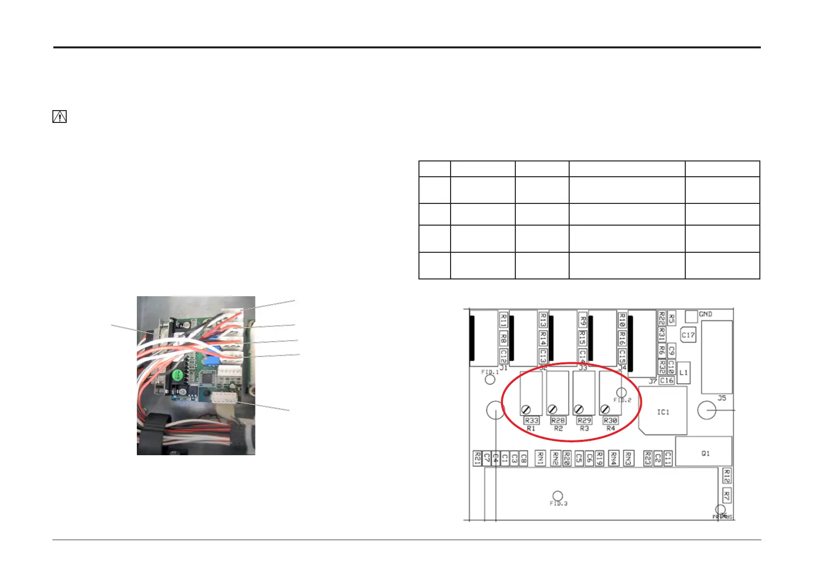
4. Remove all connectors from the PCB ”F” (x5).
5. Pinch the barbs of the pins and remove PCB ”F”.
Adjustment
1. Check perform calibration of trim potentiomenters according to table below.
2. Use an Ohm meter or a Multi meter with appropriate sensitivity.
3. After Calibration is performed and a Cover Feeder is installed perform DSD calibration
(ADJ 9.9)
Replacement
1. Reverse removal procedure.
Perform next section, Adjustment, before connecting
F.P1
F.P3
F.P4
F.P6
F.P5
F.P2
Pot Value Measure Component Module
R1 2.2 - 2.3KΩ J1, pin 1
& 3
Not in use
R2 Not in use
R3 2.2 - 2.3KΩ J3, pin 1
& 3
Q37 Hall sensor M23
thickness motor
BM Thickness
sensor
R4 9.5 - 10.5KΩ J4, pin 1
& 3
Not in use