Plockmatic BM3050 system 27 August 2019 4. Troubleshooting (RAP)
4-44
CT-503 Waste Bin Full Sensor CT-Q11 activated
Fault code indicates that at “initialization” or during a run,
the Waste Bin Full Sensor CT-Q11 was blocked exceeding timeout.
Initial Actions
• Enter Service (GP 1)
• Check sensor CT-Q11 according to GP4
• Ensure that the Waste Bin Full Sensor CT-Q11 (PL 12.10) is clean.
• Ensure that the Waste Bin Full Sensor CT-Q11 is properly connected.
• Ensure that plug A.P1 and A.P15 on the CPU/Controller PCB “A” (PL 12.12) is
properly connected.
• Ensure that plug G.P1 and G.P2 on the I/O Extension PCB “G” (PL 12.12) is
properly connected.
Procedure
Disconnect plug A.P1 from CPU/Controller PCB A.
Measure between pins A.J.1-10 and A.J1-25 (5V and Ground).
The voltage is 5 VDC ±10%?
Y N
Replace CPU / Controller PCB “A” (REP 13.23 CPU / Controller PCB “A”)
Disconnect plug G.P1 from I/O extension PCB “G”.
Measure between G1-3 and G1-5 (Signal 5V and Ground).
The voltage is 5 VDC ±10%?
Y N
Replace Extension PCB “G” I/O (REP 13.29)
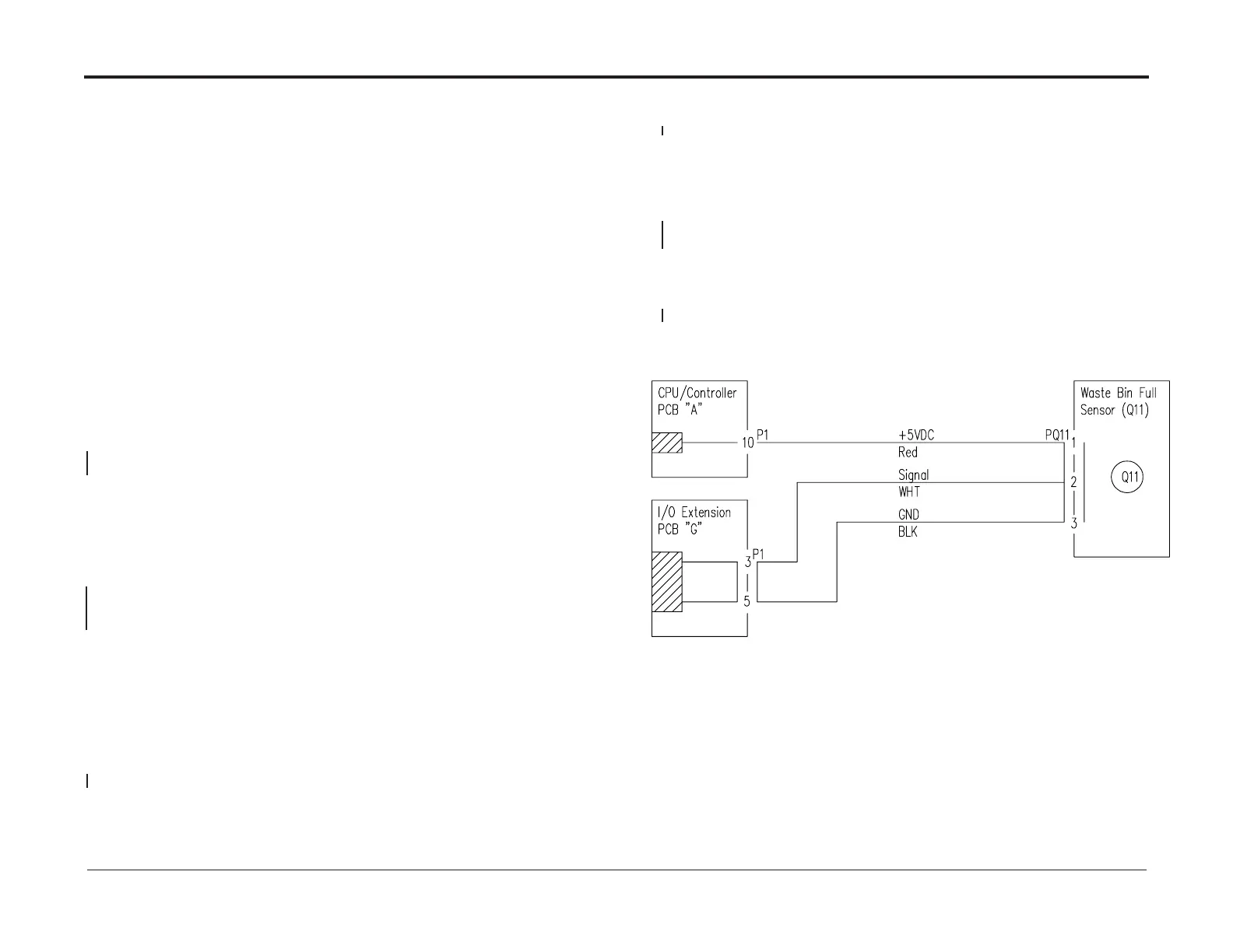
• Disconnect plug Q11 from Waste Bin Full Sensor (CT-Q11).
• Check wire for continuity / short circuit from the white wire at plug Q11 to G.P1-3.
• Check wire for continuity / short circuit from the black wire at plug Q11 to G.P1-5.
• Check wire for continuity / short circuit from the red wire at plug Q11 to A.P.1-10.
There is continuity and no short circuit?
Y N
Repair wire harness
Connect plug A.P1 to CPU/Controller PCB A and plug G.P1 to I/O extension PCB “G”.
Check for voltage at the P/J Q11 connector between
pins 1 (red wire, 5 V) and 3 (black wire, Ground)
The voltage is 5 VDC ±10%?
Y N
Repair wire harness
Replace Q11 from Waste Bin Full Sensor CT-Q11 (REP 12.23)
The Waste Bin Full Sensor (CT-Q11) works OK?
Y N
Replace the Ribbon Cable (PL 12.12) between CPU/Controller PCB “A” and
I/O Extension PCB “G”.
The Waste Bin Full Sensor (CT-Q11) works OK?
Y N
Replace CPU / Controller PCB “A” (REP 13.23 CPU / Controller PCB “A”)
Exit