Plockmatic BM3050 system 27 August 2019 4. Troubleshooting (RAP)
4-221
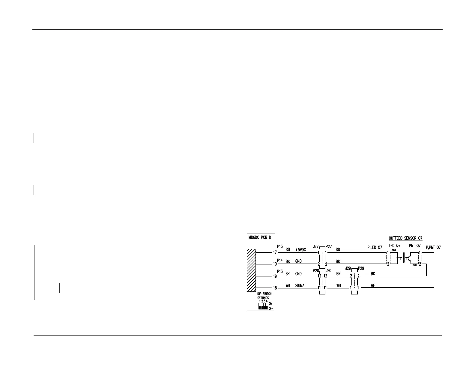
SQF-016 Exit Sensor SQF-Q7 Faulty
Fault code indicates that the Exit Sensor SQF-Q7 is faulty.
Initial Actions
• Ensure that the sensor Q7 is clean (PL 11.14).
• Ensure that Q7 is properly installed (REP 11.14 SQF-Q7 Exit Sensors).
• Ensure that jack/plug J29/P29, J20/P20, J27/P27 in the Square Folder is connected.
Procedure
• Disconnect plug D.P13 and D.P14 from MD6DC PCB ”D”.
• Measure between J.13-17 and J.14-10 (5V and GND).
The voltage is 5 VDC ± 10%.
Y N
Replace MD6DC PCB ”D”.
• Disconnect plug from Exit LED sensor Q7.
Check wire for continuity for black wire Q7 to D.P14-10 and the red wire Q7 to D.P13 17.
• Check for short circuit between red/black wires and between red/black wires to chassis/GND
There is continuity for all wires and no short circuit
Y N
Replace/Repair Wire Harness.
• Connect plug D.P13 and D.P14 to PCB ”D”.
• Disconnect plug from Exit photo transistor sensor Q7.
• Measure between black wire Q7 and white wire Q7 (Signal and GND).
The voltage is 5 VDC ± 10%.
Y N
Disconnect plug D.P13 from PCB ”D”.
Measure between J.13-18 and J.13-19 (Signal and GND).
The voltage is 5 VDC ± 10%.
Y N
Replace MD6DC PCB ”D”.
Replace/Repair Wire Harness.
• Replace Exit LED sensor (REP 11.14 SQF-Q7 Exit Sensors)
• Replace Exit photo transistor sensor Q7 (REP 11.14 SQF-Q7 Exit Sensors).