Plockmatic BM3050 system 27 August 2019 3. Repairs and adjustments (REP and ADJ)
3-188
Parts List on PL 12.12
CAUTION:
ESD Hazard! ESD (Electrostatic Discharge) can cause hardware crashes,
data and/or communications problems. Failure to use proper ESD procedures will cause
damage to electronic components (eg: PCBs). ESD problems can be minimized by main-
taining all machine ground connections, ensuring the proper handling of circuit boards/
sensors.
Use ESD protection when working near PCBs. Failure to use ESD protection is likely to
result in a PCB failure.
Removal
1. Turn off the main power and disconnect the power cord.
2. Remove the Rear Cover (REP 12.0 Front and rear cover).
3. If possible, retrieve data stored in the EEProm memory (addresses 2, 3 and 4)
prior to disconnecting the PCB.
If not possible to retrieve data before changing the PCB, replace the EEProm chip from
new PCB with EEProm chip from the old PCB to retrive these data after installation of
the new PCB.
If not possible to retrive any data from the old EEProm, go to section 5 (CT EEProm
reset), when the new PCB is installed.
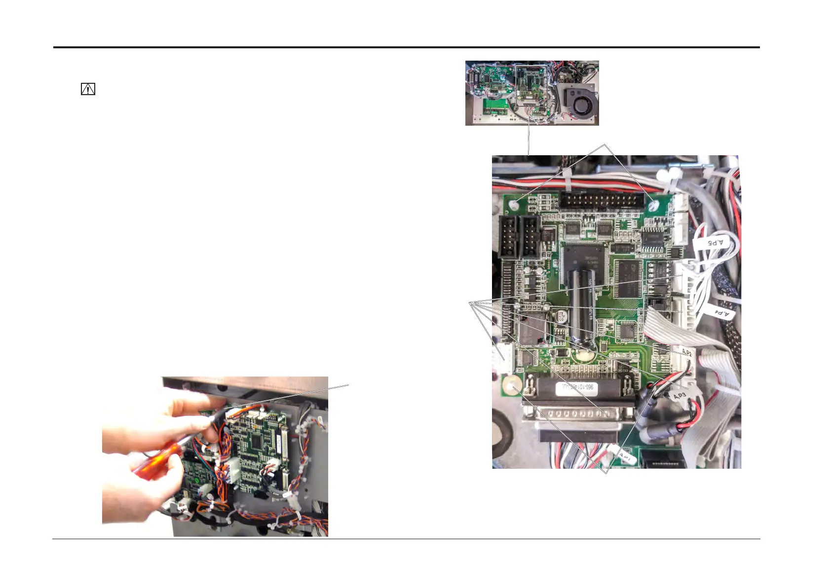
4. Remove screw and fold out PCB [A].
5. Disconnect connectors (x6) [B].
6. Release PCB from plastic studs (x4) [C].
7. Remove CPU Controller PCB ”A”.
Replacement
1. Reverse removal procedure.
2. A new CPU / Controller PCB ”A” must be loaded with S/W. Refer to section 5.
REP 13.23 CPU / Controller PCB “A”
[A]
[C]
[C]
[B]