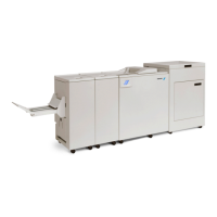
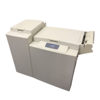
Plockmatic BM3050 system 27 August 2019 1. Installation Procedure
1-30
1.5 CST INSTALLATION
If you don’t have a CST, proceed to next section.
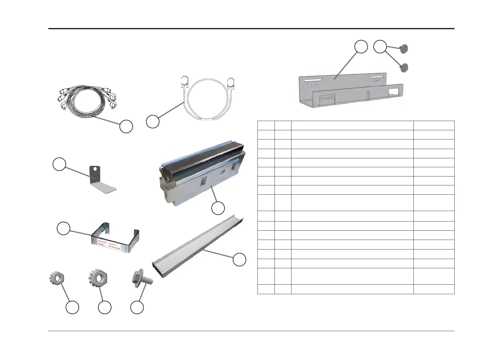
Item Q´ty Description Part no*
A 1 Power cord EUR 87156
A 1 Power Cord USA 87157
A 1 Power Cord AUS/CHN 60122
A 1 Power Cord GBR 88530
A 1 Power Cord Swiss 93464
A 1 Power Cord Danish 93465
B 1 Communication Cable 450239
D 1 Infeed Docking Bracket (for docking to
ACF510)
122-107005
E 1 Feeler Gauge 0,5mm 122-108011
F 1 Cable protector 890700
G 1 Intermediate Cover (for docking to ACF510) 122-108737
H 4 Nut M4 (for installing item G) 98055
I 2 Nut M6 98056
J 2 Screw M4x10 (for installing item D) 99399
K 1 Female Docking Bracket
(for docking to BM)
122-109998
L 2 Screws M6S M6x12 washer o18x1,6 99400
1.5.1 ACCESSORY CHECK
A
B
D
F
G
E
* Part numbers are subject to change.
Please refer to Spare Part Manual for correct numbers.
K L
H I J


 To Next Page