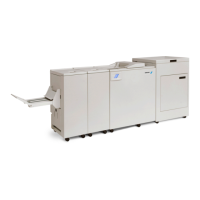
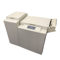
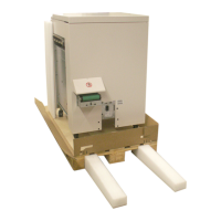
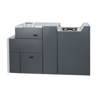
Plockmatic BM3050 system 27 August 2019 1. Installation Procedure
1-31
1.5.2 INSTALLATION PROCEDURE
1
2
3
4
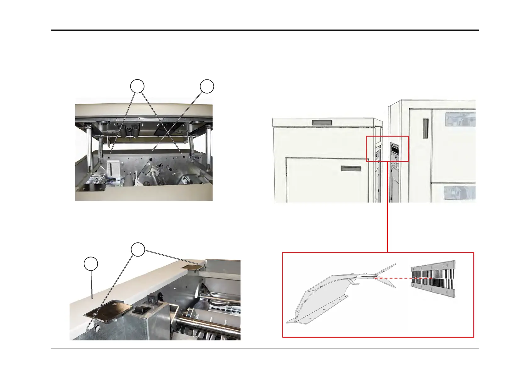
1. Remove rear cover by loosening screws 1.
Lift cover over edge 2.
2. Remove front cover by loosening screws 3.
Open Slide Door slightly and lift/remove front cover 4.
3. Adjust height to match upstreams device.
As a general rule, the exit path of the upstream device should be
slightly shifted down with respect to to the infeed path of the CST
(see picture below).


 To Next Page