Plockmatic BM3050 system 27 August 2019 3. Repairs and adjustments (REP and ADJ)
3-248
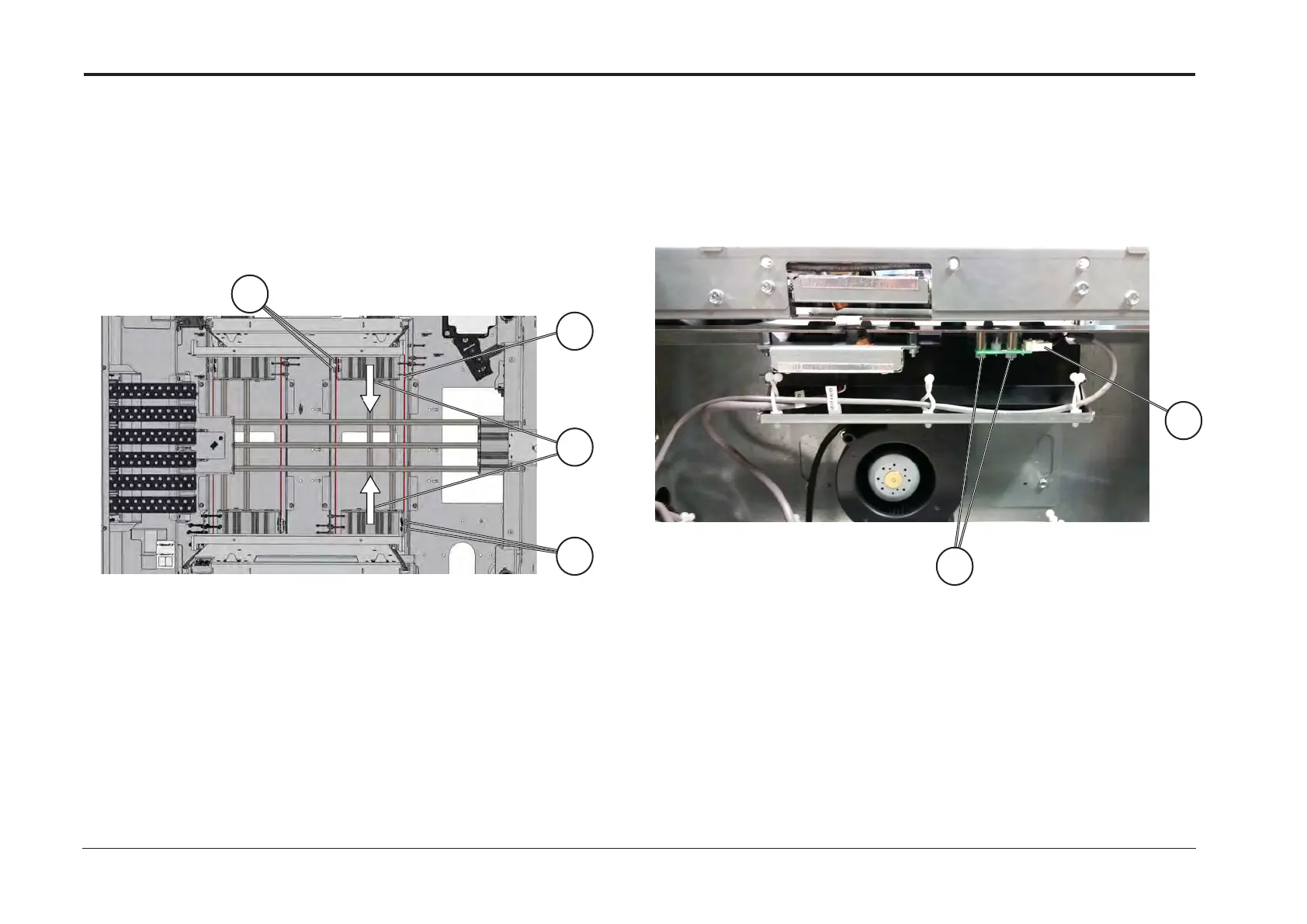
1. Remove Tray Table (REP 15.9)
2. Remove screws [A]
3. Loosen screws [B]
4. Remove cable [C]
Replacement
Reverse removal procedure
Note!
Before torquing screws [B], move the sleds [D] as far in as possible
1. Open tray
2. Disconnect connector [A]
3. Remove screws [B]
4. Remove PCB LED
Replacement
1. Reverse removal procedure
2. Perform Calibration Optical DSD according to BM3050 Operator
Manual, VF602 Sensor Calibration Section
B
A
(VF602 Spare Parts Manual, PL2.2 Item 8) (VF602 Spare Parts Manual, PL2.3 Item 2)
REP 15.18 Side Guide Adjustment Cable REP 15.19 PCB LED (Q101LED, Q201LED) (Optical DSD)
Relevant parts are painted red.
A
D
C
B