Plockmatic BM3050 system 27 August 2019 5. Service tables (GP)
5-47
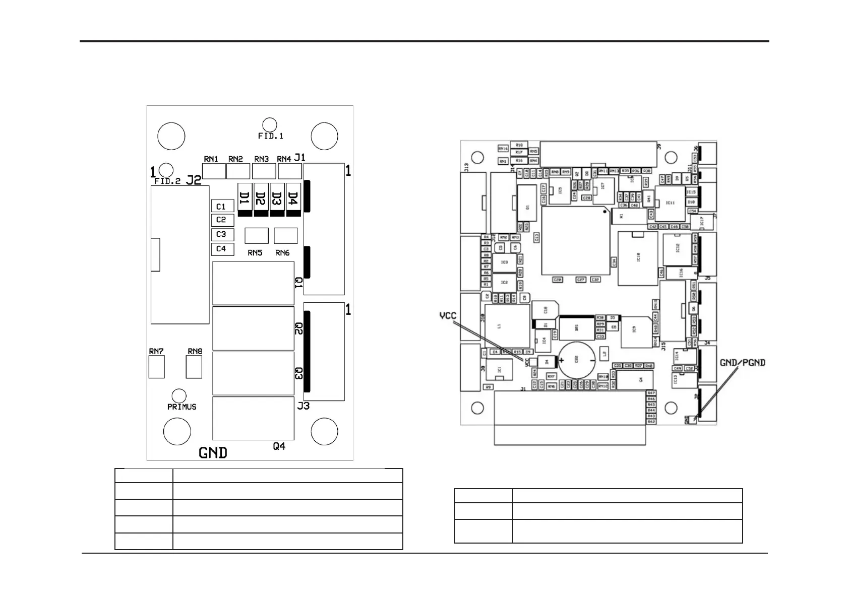
LED Description
D1 SW2 (Q8) activated, slide inner position
D2 SW3 (Q9) activated, to cover closed
D3 Q11 activated
D4 Q12 activated, optional
Test points Description
VCC +5VDC measured from GND/PGND
GND/
PGND
Ground / Power Ground is the minus when measuring voltage
in the machine such as, VCC (+5VDC), +24VDC and +48VDC
GP 45 CST I/O 4IN4OUT PCB “G“
Purpose
The purpose is to provide an explanation of the LED indications on the PCB.
GP 46 CST CPU / Controller PCB “A“ Test points
Purpose
The purpose is to provide test points on the PCB.